Rain sensor

a sensor and rain sensor technology, applied in the field of rain sensors, can solve the problems of snr degradation, difficulty in mounting, and mounting difficulties, and achieve the effects of reducing the probability of rain sensor malfunction, enhancing operation reliability, and preventing snr degradation

Active Publication Date: 2013-06-25
HAN SEA YEOUN
View PDF13 Cites 134 Cited by
  • Summary
  • Abstract
  • Description
  • Claims
  • Application Information

AI Technical Summary

Benefits of technology

[0026]Unlike a sensing method using the windshield as an optical waveguide or a method where a light source emitting signal light and a light receiving element are arranged to face each other, or a method where the a light source and a light receiving element are disposed serially along the same direction, a rain sensing method of the present invention has an adequate effect on reducing the probability of malfunctioning of the rain sensor by increasing the raindrop sensing probability where the light emitting light sources are disposed the receiving element so that the raindrops fallen on the surface of the windshield can be monitored over a wide area.
[0027]According to the present invention, a novel rain sensor having a simplified optical system for an easy installment, and capable of preventing degradation in the SNR affected by the light reflected from the surface of the windshield except from the raindrops by installing the light source transmitting light into the windshield and the light receiving element collecting reflected light from the raindrops inclined with respect to the surface of the windshield, and designed to exclude optical signals caused by the alternating motion of the wipers so that the effect from the headlights of another person's vehicle during the operation of the wipers is prevented so as to enhance operation reliability significantly can be provided.

Problems solved by technology

Among the above described methods, the first method requires a complicated optical system and brings on difficulties in mounting since the optical coupler must be in close contact with the windshield and maintain precise incident angle when the sensing signal light is transmitted into the windshield so as to be guided inside thereof.
Disadvantage of the third method is a narrow and small sensing area for a light source and light receiving element set since it requires many light source and light receiving element sets to detect raindrops falling on a wide area due to the serial arrangement of the light source and light receiving element.
In summary, a conventional rain sensing method using internal light guiding phenomenon inside of the windshield requires a complicated optical system and brings on difficulties in mounting; in a method measuring reflecting light from the raindrops wherein the light source and the light receiving element are located apart opposing each other, the SNR is degraded due to the reflection from the surface of the windshield; a reflection type method wherein a light source and a light receiving element are serially arranged, has a narrow and small raindrop sensing area.
Since the speed control system for such wipers provides only a couple of steps, it is impossible for a driver to operate the wipers at a desired speed corresponding to the level of rainfall.
Even in the products developed to solve above described problems, the SNR is degraded due to the large amount of reflection from the windshield in addition to the optical signal reflected from the raindrops therefore expected performance in sensing efficiency cannot be achieved.
Furthermore, in a conventional method, optical signals caused by the alternating motion of the wipers are also being received; hence the sensing efficiency is getting worse since it is affected by headlights from another person's vehicle.
In other words, during the operation of the wipers headlights from another person's vehicle could be received in addition to the reflected light from the raindrops thereby causing malfunction etc.

Method used


Image

  • Rain sensor
  • Rain sensor
  • Rain sensor

Examples


Embodiment Construction

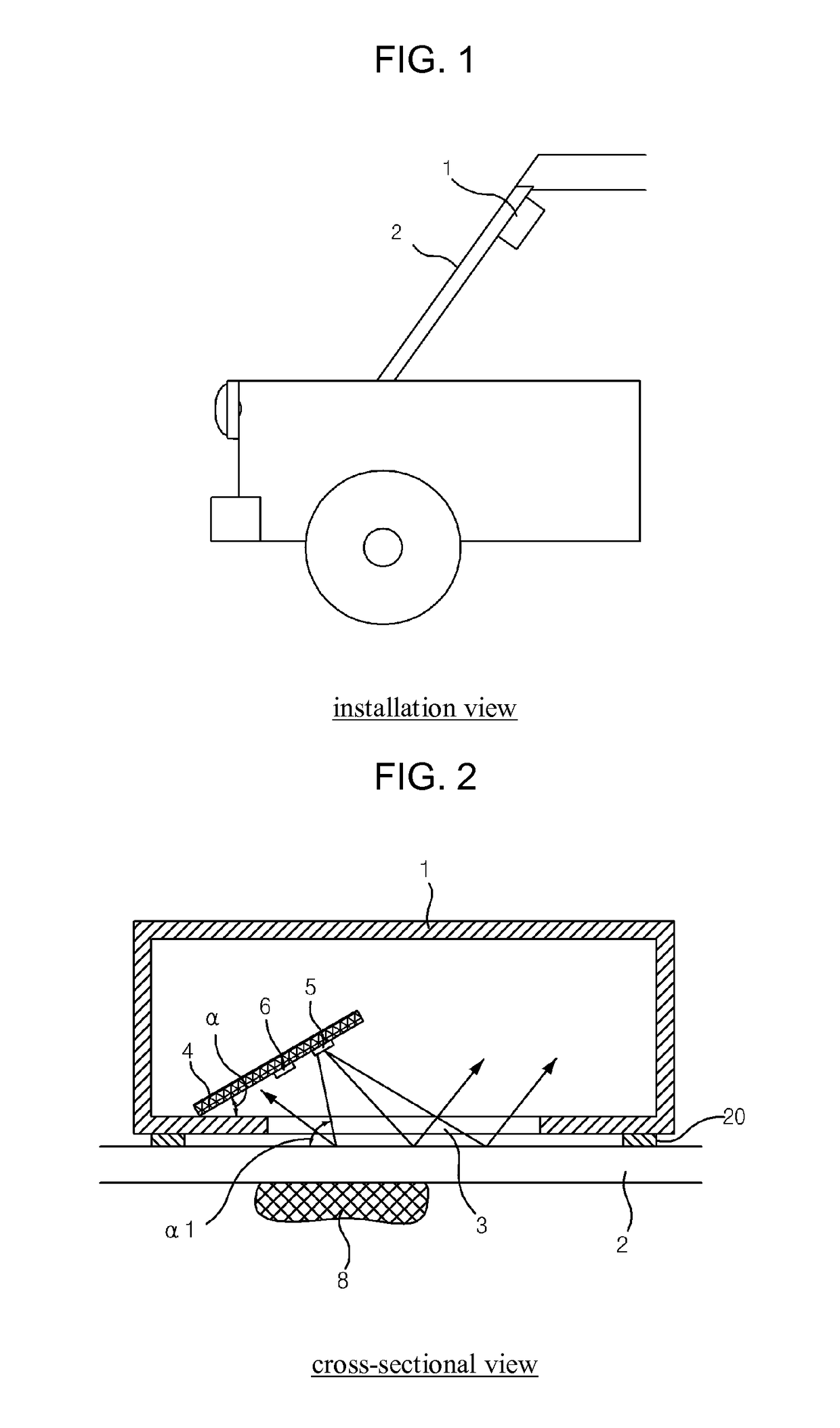
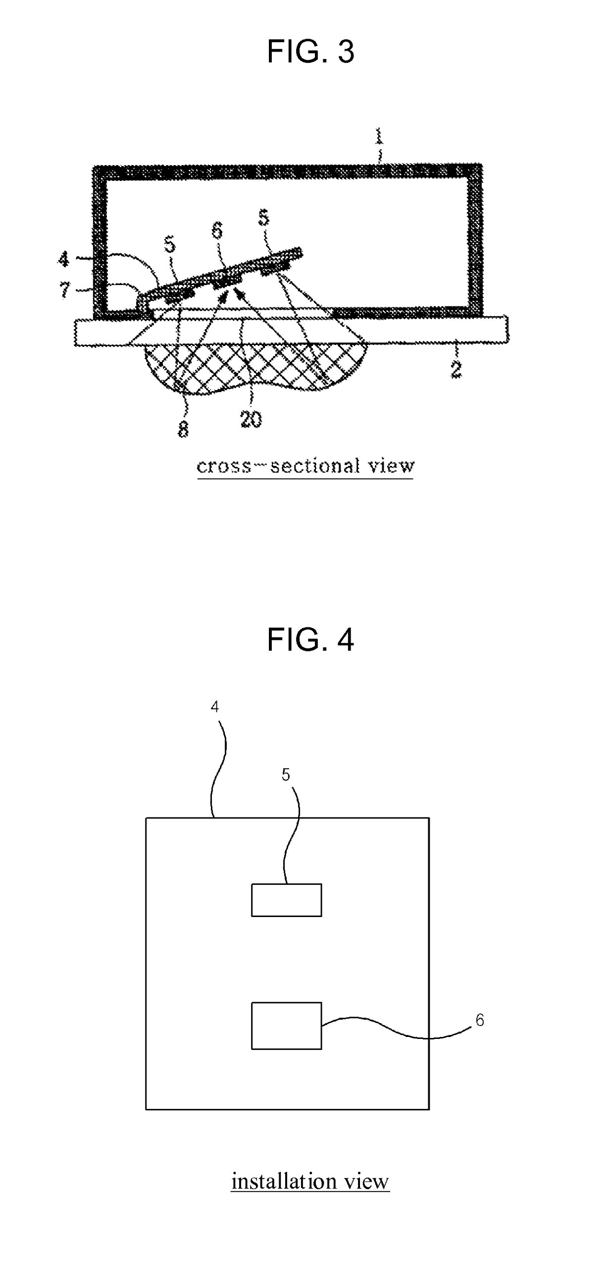
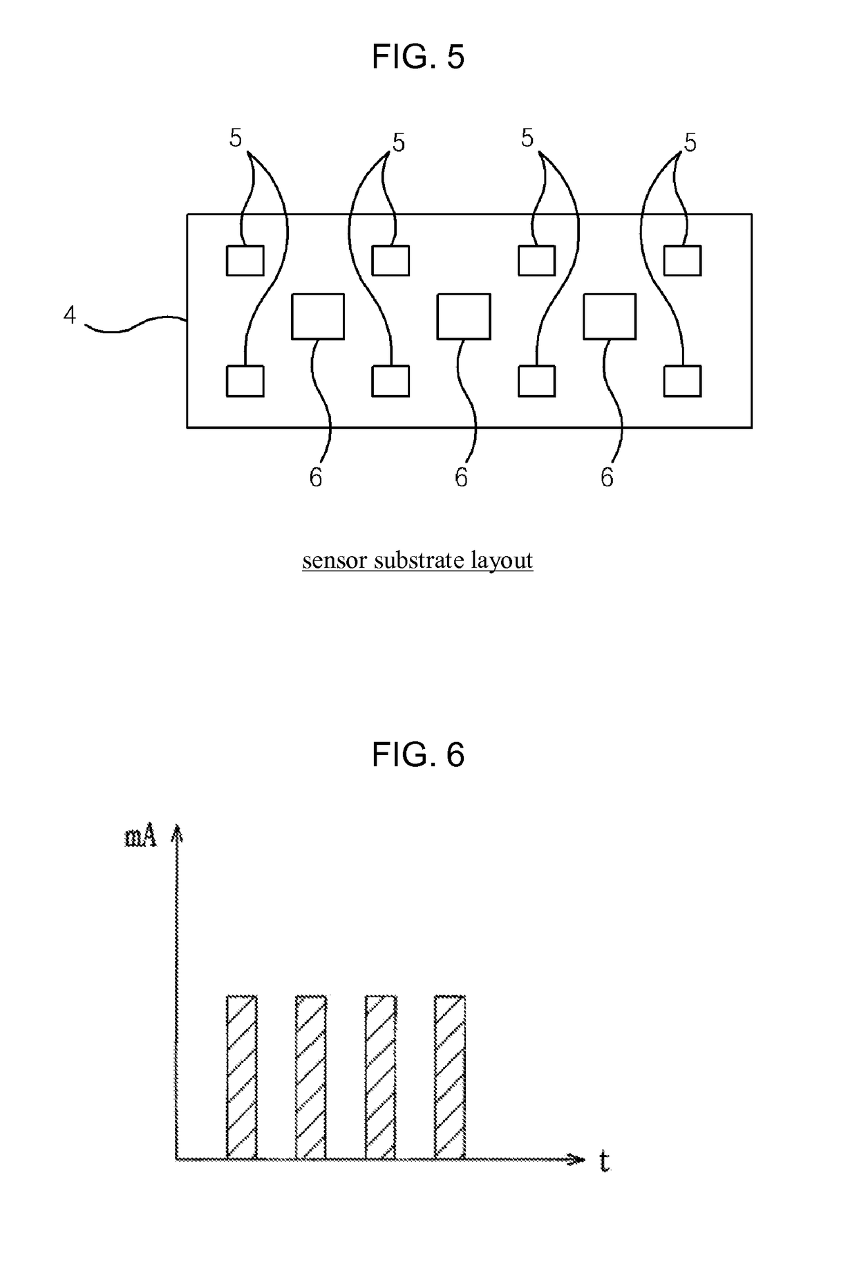
[0035]A rain sensor comprising a light source (5) radiating signal light according to the generated signal in a transmitter (11), a light receiving element (6) for receiving light in the unit sensing area facing towards the light reflected from the raindrops by the radiating light of the light source (5) and arranged with surrounding four light sources (5), an infrared filter installed in the opening formed at the one side of the housing (1) of the rain sensor, and a receiver (9) excluding noise components caused by the reflection from the surface of the windshield (2) and extracting only the modulated frequency component of the signal light to determine the amount of existing raindrops on the surface of the windshield so as to minimize the effect of ambient light and enhance the raindrop sensing probability is provided.

[0036]According to the present invention, a rain sensor comprising a light source (5) radiating light into the windshield (2); a light receiving element (6) performi...


PUM


Abstract

During rain, including a light source (5) for radiating light such that the light is transmitted through a vehicle window (2), a light receiving element (6) for sensing an optical signal when the light radiated from the light source (5) is reflected from the raindrop fallen on the vehicle window (2) and performing a photoelectric transduction, and a receiver (9) for receiving the photoelectrically transduced signal from the light receiving element (6) and judging the level of rainfall. The light source (5) and the light receiving element (6) are inclined with respect to the surface of the vehicle window (2) such that the light of the light source (5) directly reflected from the vehicle window (2) exits to the outside of the light receiving element (6) and the light reflected from a raindrop (8) on the vehicle window (2) is received by the light receiving element (6) to operate a vehicle wiper.

Description

TECHNICAL FIELD[0001]This invention relates to a rain sensor attached to a windshield for determining the level of rainfall by receiving the amount of the light reflected towards the light source from the raindrops fallen on the windshield on which the sensor is attached.[0002]This invention further relates to a raindrop sensor immune to ambient light except the optical signal reflected from the raindrops, thereby enhancing the sensing efficiency of the level of rainfall.BACKGROUND ART[0003]Up to date, conventional rain sensors have been using the methods of: injecting an optical signal into the windshield to determine the level of rainfall by detecting the decrease in the amount of guided light through the windshield reaching the light receiving element attached to the opposite side of the light source when the raindrops fall on the windshield; transmitting a slanting signal light into the windshield to determine the level of rainfall by detecting the change in the amount of light ...

Claims


Application Information

Patent Timeline
Patent Type & Authority Patents(United States)
IPC IPC(8): H02P7/00
CPCB60S1/0837G01N21/35G01N21/4738G01N21/3554G01N21/55G01N2201/0625
Inventor HAN, SEA YEOUN
Owner HAN SEA YEOUN
Why Eureka
Try Eureka