Current drive circuit and drive method thereof, and electroluminescent display apparatus using the circuit

a current drive and circuit technology, applied in static indicating devices, instruments, solid-state devices, etc., can solve problems such as inability to completely eliminate, generate irregularities, and produce display heterogeneity, and achieve excellent display characteristics, suppress irregularities, and suppress current irregularities

Inactive Publication Date: 2012-01-10
CASIO COMPUTER CO LTD
View PDF27 Cites 0 Cited by
  • Summary
  • Abstract
  • Description
  • Claims
  • Application Information

AI Technical Summary

Benefits of technology

[0019]A current drive apparatus according to the present invention has an advantage to suppress irregularities in currents between output terminals of a current drive apparatus which operates by applying currents to a plurality of loads, and also suppress irregularities between chips when the current drive apparatus constructed by a plurality of driver chips. Further, it has an advantage to obtain the excellent display characteristic with display irregularities being suppressed in a display apparatus including the current drive apparatus.

Problems solved by technology

Therefore, when irregularities are generated in current values of the drive currents outputted from a plurality of the driver chips, irregularities occur in the light emitting state in each display pixel (brightness gradation of the light emitting element), and the display heterogeneity is produced.
However, in the field of a semiconductor manufacture technique, there is known the fact that irregularities are necessarily generated in the element characteristic of function elements such as transistor elements, resistance elements or capacitance elements formed on the same semiconductor chip.
Such irregularities in the element characteristic can be suppressed to some degree by, e.g., optimizing manufacturing processes, but they cannot be completely eliminated.
Further, there has been reported the fact that irregularities in the number of impurity atoms in channels become relatively actual with a reduction in design minimum dimension applied to the transistor elements and irregularities are thereby generated in a threshold value or the mobility.
Therefore, there is a problem that it is very difficult to greatly improve the irregularities in the drive currents between the output terminals of the driver chips caused due to the above-described irregularities in the element characteristic by using only a technique of optimizing the manufacturing processes.
Furthermore, since there is a limit in the number of output terminals which can be set in one semiconductor chip due to a problem of an increase in signal delay owing to an increase in wiring length or to a reduction in production yield with an increase in the number of elements in one chip, the data driver must be necessarily configured by using a plurality of the driver chips.
If the semiconductor chips are different from each other, irregularities in the drive currents between the output terminals further become large, and it is very difficult to suppress irregularities in the drive currents in the same driver chip while suppressing the same between the driver chips.
In this technique, when the number of the output terminals provided to the same driver chip is increased, adjustment of each current setting resistance becomes complicated, adjustment requires a long time and cost and a resistance setting area in the circuit configuration becomes large.
Therefore, it is not suitable as a technique to suppress irregularities in the drive currents between the respective output terminals.
Therefore, the data driver including the driver chips and thus the apparatus scale of the display are increased, and there is a problem that a product cost is increased.
Moreover, as described above, in the display in recent years, although realization of further clearness of gradation display is demanded with realization of high definition in the display image quality, the light emitting element type display which has been currently developed has a problem that it has not reached establishment of a technique to generate an analog output signal which can realize the sufficient gradation display when generating a drive current having an analog signal component from a digital input signal which becomes display data by digital-to-analog conversion.

Method used


Image

  • Current drive circuit and drive method thereof, and electroluminescent display apparatus using the circuit
  • Current drive circuit and drive method thereof, and electroluminescent display apparatus using the circuit
  • Current drive circuit and drive method thereof, and electroluminescent display apparatus using the circuit

Examples


first embodiment

of Current Drive Apparatus

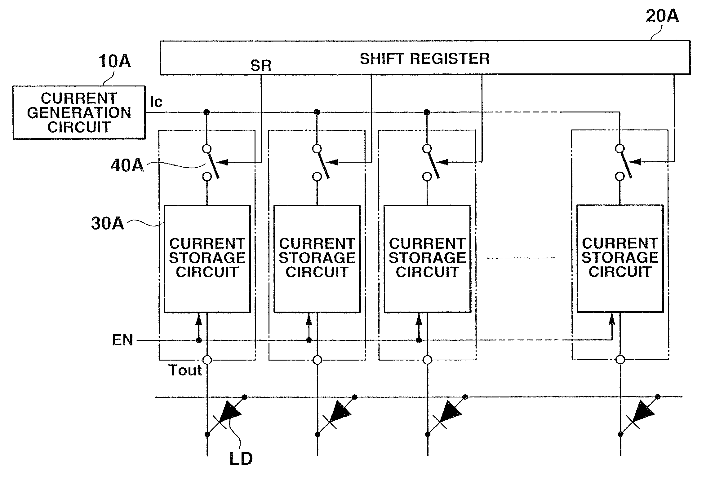
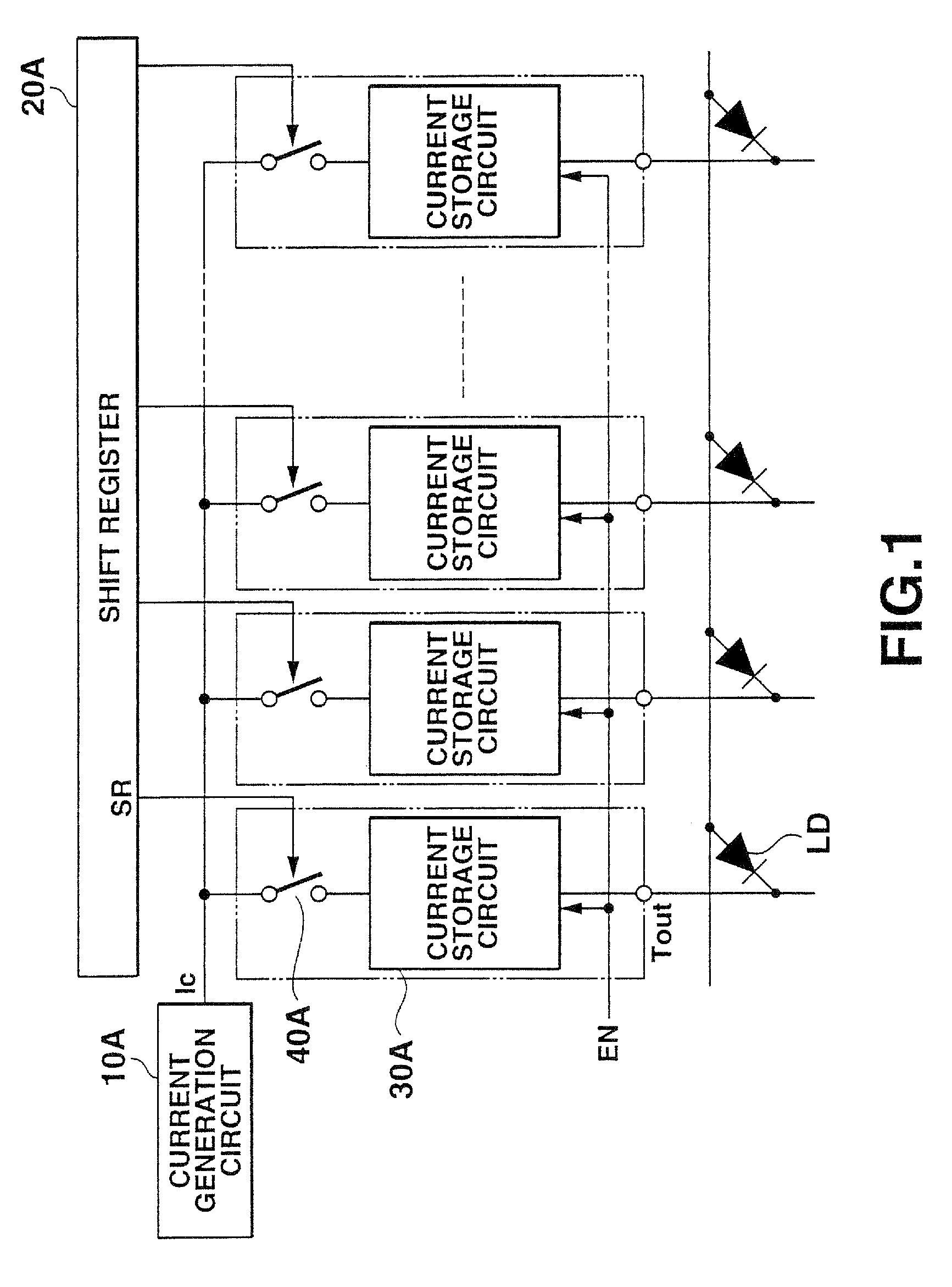
[0050]FIG. 1 is a primary structural view showing a first embodiment of a current drive apparatus according to the present invention.

[0051]The current drive apparatus according to the first embodiment has a structure to sequentially hold a current with a predetermined current value supplied from a single current generation circuit in a current storage circuit provided in accordance with each output terminal and thereafter simultaneously output the currents to loads (display elements) through each of the output terminals.

[0052]As shown in FIG. 1, the current drive apparatus according to this embodiment comprises: a single current generation circuit 10A which generates and outputs an operating current Ic having a predetermined current value used to control a drive stage of each load LD (display element) connected to each of a plurality of output terminals Tout; a shift register 20A which sets a timing when supplying the operating current Ic supplied from the ...

second embodiment

of Current Drive Apparatus

[0097]FIG. 6 is a primary structural view showing a second embodiment of a current drive apparatus according to the present invention. Here, the same or equivalent reference numerals denote structures equivalent to those in the above-described first embodiment, thereby simplifying or eliminating their explanation.

[0098]The current drive apparatus according to the second embodiment includes a pair of current storage sections in accordance with an output terminal to which a load is connected, and is constituted to execute in parallel an operation to sequentially fetch a current having a predetermined current value supplied from a single current generation circuit by the current storage section on one side and hold a corresponding voltage component and operation to simultaneously output the current based on the voltage component which has been already held in the current storage section on the other side through the output terminal.

[0099]As shown in FIG. 6, th...

third embodiment

of Current Drive Apparatus

[0109]FIG. 7 is a primary structural view showing a third embodiment of a current drive apparatus according to the present invention. Here, the same or equivalent reference numerals denote the structures equivalent to those in the first and second embodiments, thereby simplifying or eliminating their explanation.

[0110]The current drive apparatus according to the third embodiment has current storage sections on two stages provided in series in accordance with each output terminal to which a load is connected, and is constituted so as to execute an operation to sequentially hold a current having a predetermined current value supplied from a single current generation circuit by the current storage section on the front stage and an operation to hold the current supplied from the current storage section on the front stage by the current storage section on the rear stage and then collectively outputs it through the output terminal.

[0111]As shown in FIG. 7, the cu...


PUM


Abstract

A current drive apparatus for an active matrix display operates a plurality of loads, e.g. organic or inorganic EL elements, by applying a current thereto. The apparatus includes a plurality of output terminals to which the loads are respectively connected. A single current generation circuit comprising e.g. a digital to analogue converter and a current mirror, outputs an operating current having a predetermined current value. A plurality of current storage circuits are provided in accordance with the respective output terminals, sequentially sample and hold the operating current and then simultaneously output the drive currents based on the sampled operating currents to the respective output terminals. The operating current has a current value according to an input signal. The current storage circuit includes a voltage component holding section which samples the operating current outputted from the current generation circuit and holds a voltage component for driving a drive control current corresponding to a current value of the operating current for driving a second current mirror.

Description

CROSS-REFERENCE TO RELATED APPLICATIONS[0001]This application is a Divisional Application of U.S. application Ser. No. 10 / 801,172 filed Mar. 11, 2004, now abandoned which is incorporated herein by reference and which is also a Continuation Application of PCT Application No. PCT / JP03 / 08153, filed Jun. 27, 2003, which was not published under PCT Article 21(2) in English.[0002]This application is based upon and claims the benefit of priority from prior Japanese Patent Application No. 2002-187803, filed Jun. 27, 2002, the entire contents of which are incorporated herein by reference.BACKGROUND OF THE INVENTION[0003]1. Field of the Invention[0004]The present invention relates to a current drive apparatus, a drive method of the current drive apparatus, and a display apparatus using the current drive apparatus, and more particularly to a current drive apparatus including a structure to operate a plurality of loads by applying a predetermined current thereto, a drive method thereof, and a d...

Claims


Application Information

Patent Timeline
Patent Type & Authority Patents(United States)
IPC IPC(8): G09G3/30G09G3/36G09G3/20G09G3/32H01L51/50G11C5/14G11C19/00G11C27/02
CPCG09G3/3216G09G3/325G09G3/3283G11C27/028G11C5/14G11C19/00G09G3/2011G09G3/2014G09G3/32G09G2300/0866G09G2310/0221G09G2310/027G09G2310/0294G09G2300/0842G09G3/30
Inventor HATTORI
Owner CASIO COMPUTER CO LTD
Why Eureka
Try Eureka