Simplified tie restraint

a technology of tie restraints and straps, applied in the direction of neckties, garment suspenders, garments, etc., can solve problems such as unnatural appearan

Inactive Publication Date: 2000-10-17
MCNAMARA BRIAN L
View PDF5 Cites 64 Cited by
  • Summary
  • Abstract
  • Description
  • Claims
  • Application Information

AI Technical Summary

Problems solved by technology

However, both the bar and stud tend to distort or flatten the tie, and constrain the tie to the shirt, resulting in a somewhat unnatural appearance.

Method used


Image

  • Simplified tie restraint
  • Simplified tie restraint
  • Simplified tie restraint

Examples


Embodiment Construction

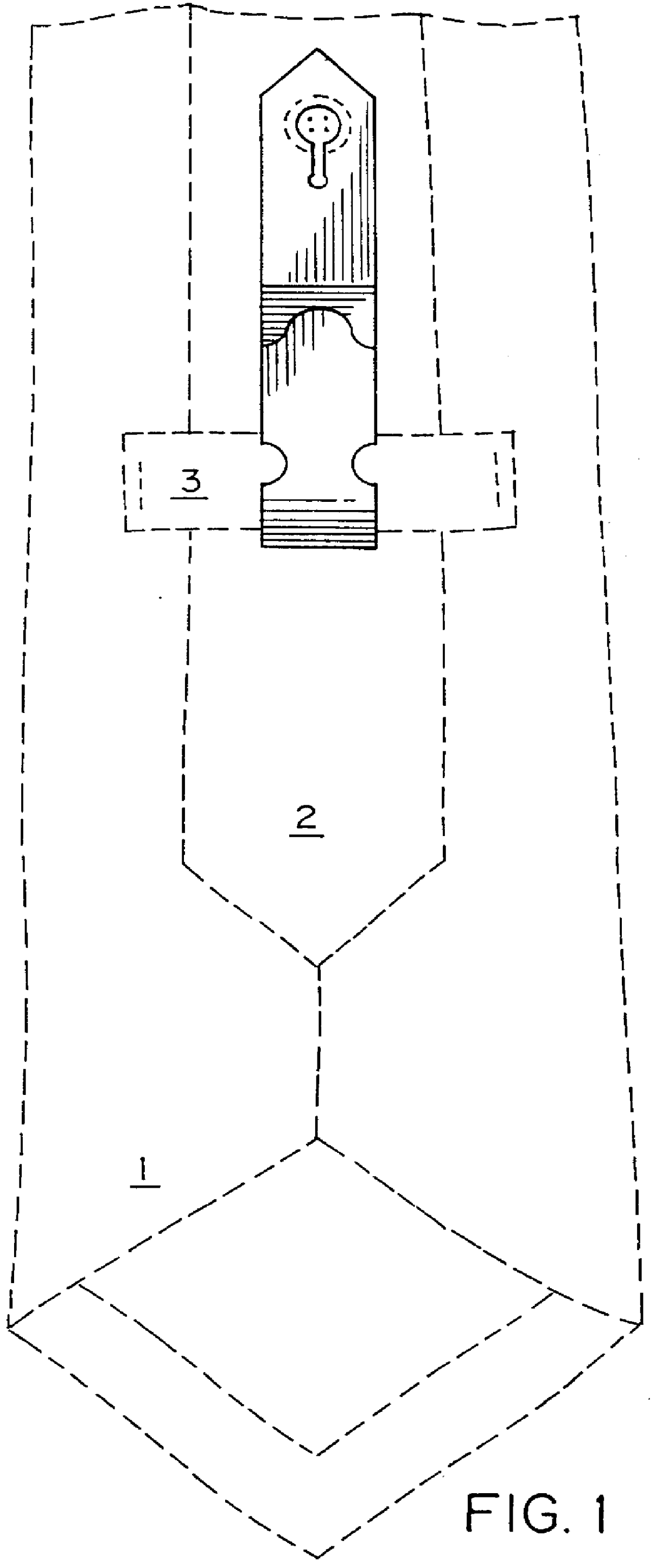
The first preferred embodiment may be understood by first referring to FIG. 1, which depicts the invention as viewed from the back, or wearer side, of the tie.

In the drawing of FIG. 1, the tie comprises a major end 1, a minor end 2, and a label 3 attached at either end laterally to the minor end, permitting the minor end to be led through the space between the major end and the label, thereby keeping the minor aligned with, and centered on the major end, so that the minor end is generally not visible when the tie is viewed when facing the wearer. The use of the label to so constrain the minor end is a very common, but not universal, use of said label.

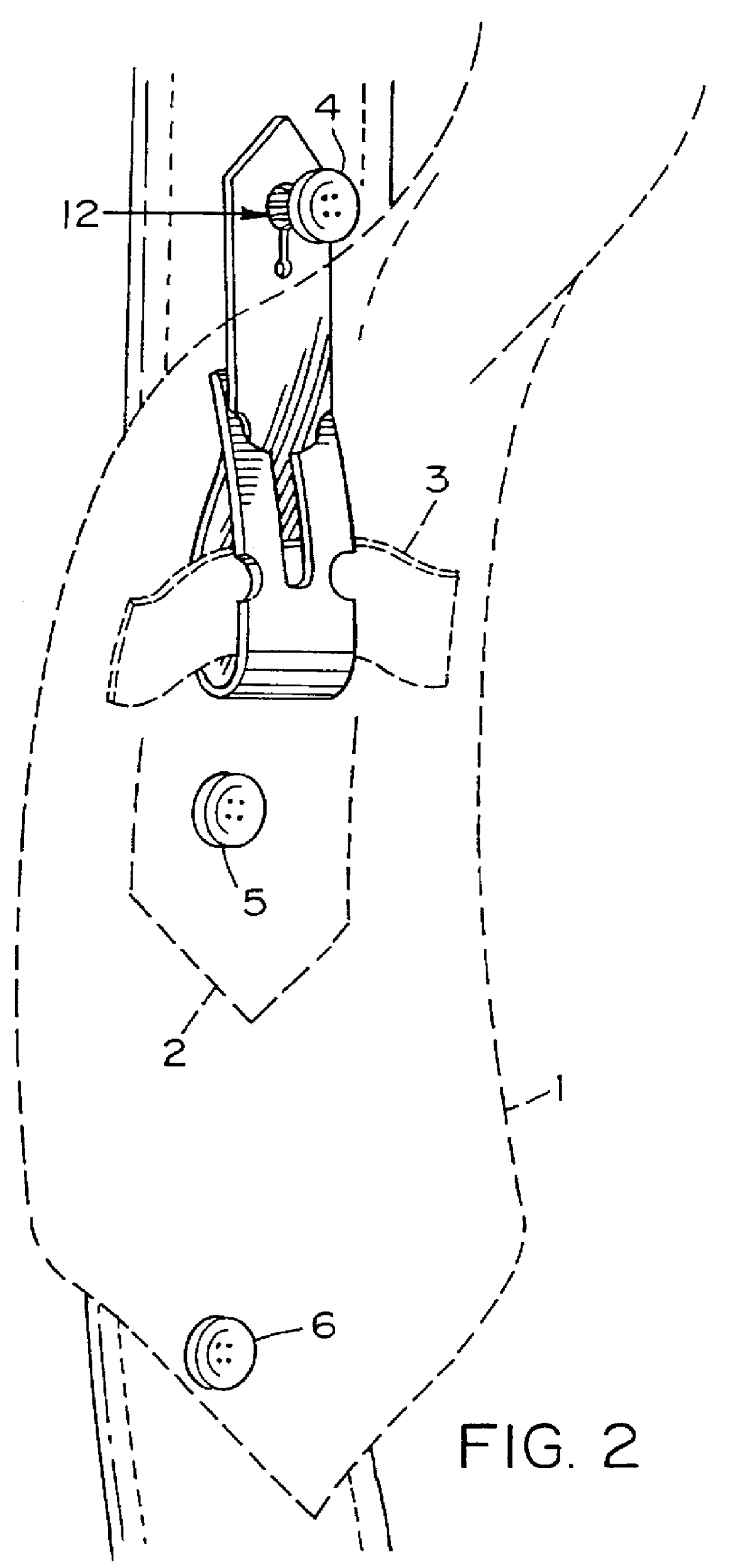
FIG. 2 shows the tie from the same viewpoint, except that in FIG. 2 the upper part of the tie is displaced to the right, so that the upper part of the tie restraint is visible, and the tie restraint is shown in a perspective view. In FIG. 2 the buttons 4, 5, and 6 of the shirt front are depicted, and button 4 is affixed to the restraint...


PUM


Abstract

An invisible tie restraint replaces the standard tie tack or tie bar for restraining a necktie onto a shirt or blouse front. The restraint is simple and inexpensive, being made of a single piece of flat treated cloth, paper or plastic. In one embodiment he restraint comprises an upper end, a lower end, and a body connecting the two ends, the body containing a multiplicity of notch pairs. The lower end contains a loop entry into which the upper end is inserted, drawing the body through until one of the notch pairs reaches a "stop" position while capturing the label of the necktie within the looped formed thereby. The restraint is attached to the shirt front by attaching a shirt button into a button hole formed in the upper end of the restraint. In other embodiments the restraint takes the form of a modified label, the label having a tab into which the button hole is formed.

Description

1. Field of the InventionThe present invention relates to tie restrains, and more specifically to tie restrains which are not visible when the wearer is viewed from the front.2. Description Relative to the Prior ArtRestraints for neck-ties or cravats worn by men, and occasionally by women, are well known. Tie bars, tie clips, studs which pierce the tie, and the like have been used for many years.The tie bar or tie clip usually contains an ornamental decoration on the front, so that an observer will view the decoration which appears as fastened to the tie. The obverse side of the tie bar is usually fastened to the front of the shirt, so that the tie is thus restrained to conform to the desired position, that is, in a vertical line centered over the front shirt buttons, and held close to the wearer's body.The tie stud operates in a similar fashion. The stud generally comprises a stud head, stud pin, and pin clasp. The stud pin generally pierces the tie, and the tie is held fast betwee...

Claims


Application Information

Patent Timeline
Patent Type & Authority Patents(United States)
IPC IPC(8): A41D25/00
CPCA41D25/003Y10T24/19
Inventor MCNAMARA, BRIAN L.
Owner MCNAMARA BRIAN L
Why Eureka
Try Eureka