Combine header height control

a technology of header height and height positioning, which is applied in the direction of adjusting devices, picking devices, agricultural tools and machines, etc., can solve the problems of increasing the possibility of header damage, reducing harvesting efficiency, and damage to the combine, so as to reduce the ingestion and impact damage of the combine, the effect of more accurate height positioning of the header and easy retrofi

Inactive Publication Date: 2001-03-20
GRAMM RICHARD
View PDF29 Cites 68 Cited by
  • Summary
  • Abstract
  • Description
  • Claims
  • Application Information

AI Technical Summary

Benefits of technology

It is another object of the present invention to provide a height sensor for an agricultural header such as on a combine which is mounted to a forward end of the header for more accurate height positioning of the header to reduce combine ingestion a

Problems solved by technology

Positioning the header too close to the soil may also result in ingestion of non-crop debris which reduces harvesting efficiency and may also cause damage to the combine.
A prime objective in crop harvesting is to cover as much ground as possible by operating at high speeds which increases the possibility of header damage caused by irregular terrain or hazards in the field.
With increased combine operating speeds, monitoring and adjusting head height is made even more difficult.
Header repairs are costly an

Method used


Image

  • Combine header height control
  • Combine header height control
  • Combine header height control

Examples


Embodiment Construction

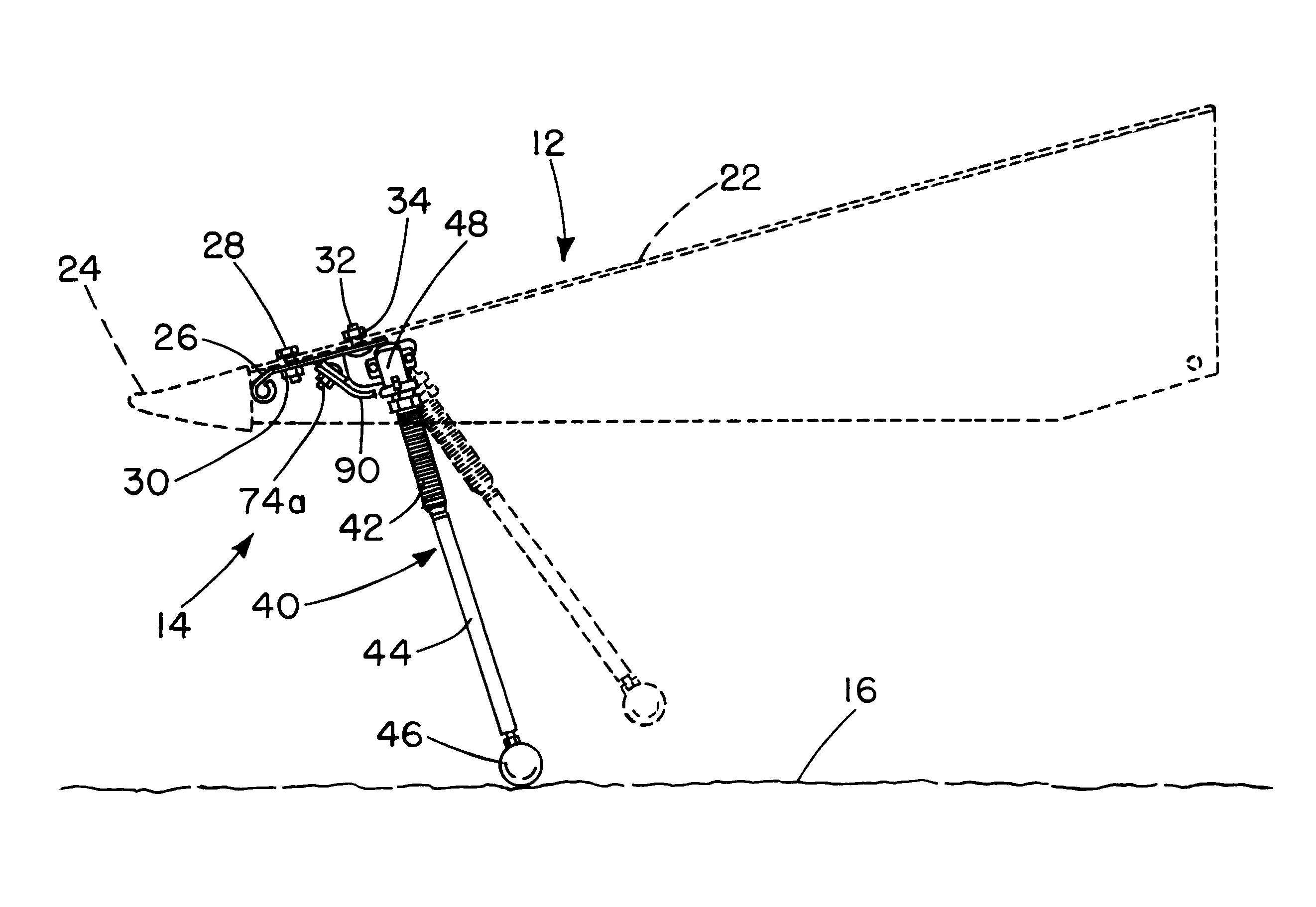
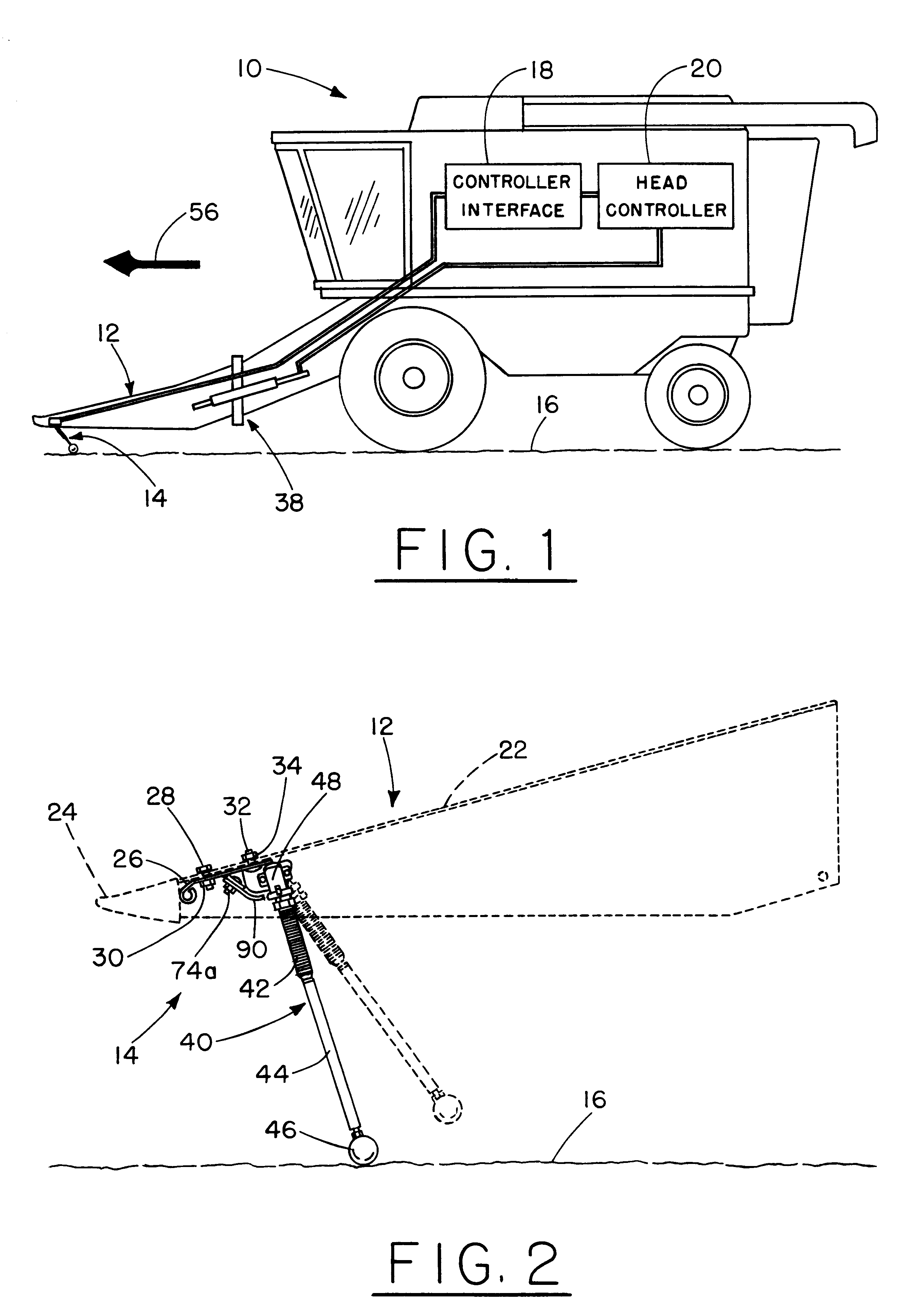
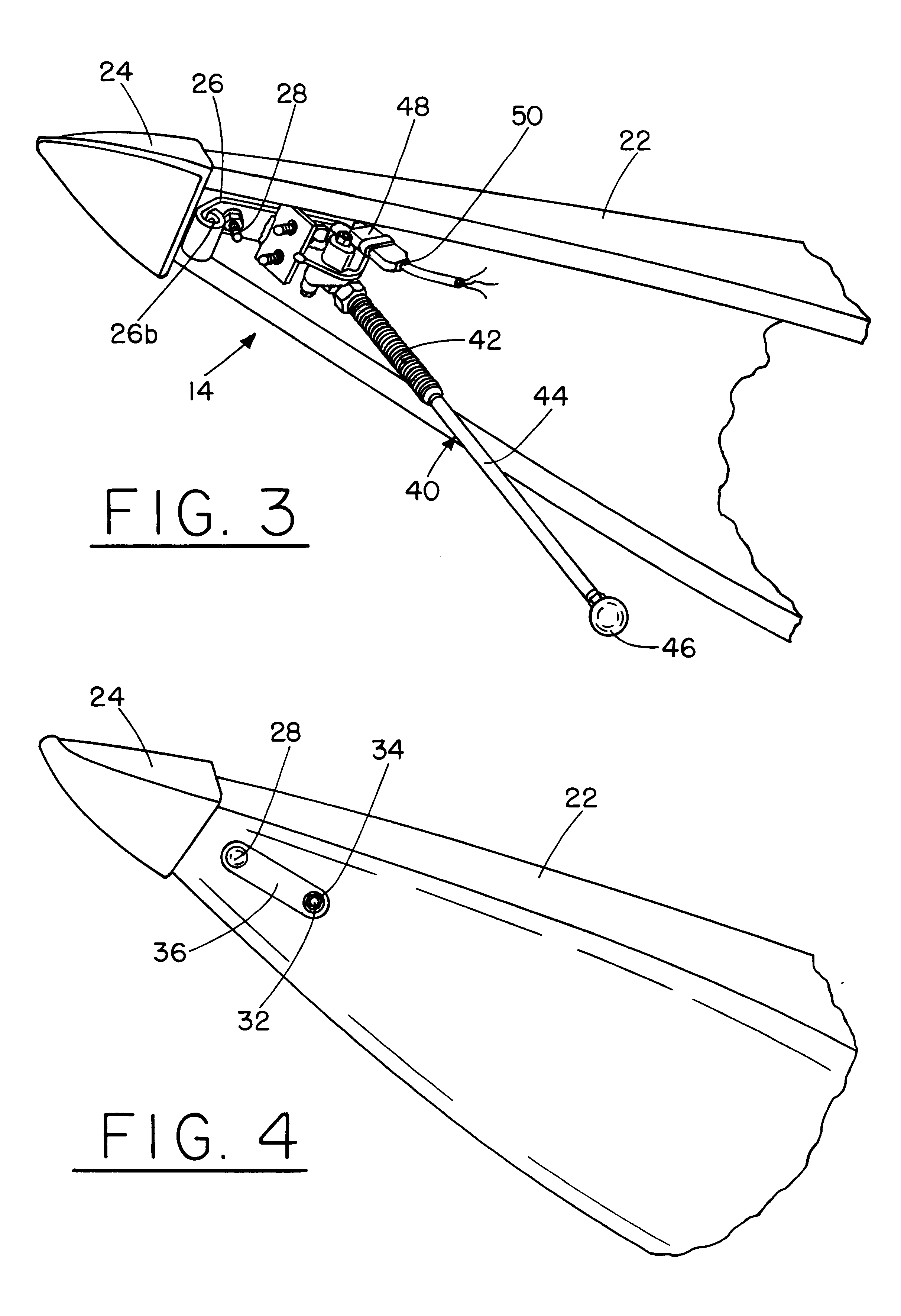
Referring to FIG. 1, there is shown in simplified schematic and block diagram form a combine 10 having attached to a forward, or leading, portion thereof a corn header 12. Corn header 12 is attached to the combine 10 by conventional means such as mounting brackets and bolts (not shown for simplicity) and includes a plurality of spaced head units adapted to pass between adjacent crop rows during harvesting of the crop. Disposed on a forward portion of one or more head units is a corn head height sensor 14 in accordance with the present invention. The corn head height sensor 14 is connected by suitable electrical means to a controller interface 18 and a head controller 20 within combine 10. In response to the detected height of the corn header 12, head controller 20 provides suitable electrical control signals to an electrically actuated, hydraulic control system 38 for controlling the lateral position of the corn header 12 as well as its height above the ground, or soil, 16 as the co...


PUM


Abstract

An arrangement for controlling the height above or depth below an irregular surface of a body moving over or below the surface includes a rotation sensor coupled to a controller responsive to an angular deflection signal output by the rotation sensor. The rotation sensor and controller are mounted to a vehicle moving over the surface such as an agricultural vehicle traversing a field. A semi-rigid, flexible arm has a first end coupled to the rotation sensor with a ground engaging member attached to a second opposed end of the arm. In one embodiment, the flexible arm includes an elongated coil spring attached to a rigid shaft and the ground engaging member is a spherical ball attached to the shaft's distal end. The coil spring is pre-loaded to a selected bending or flexure force and permits the ground engaging member to impact obstructions in the field without damage to the rotation sensor. The coil spring also prevents damage to the rotation sensor when the vehicle is reversed in direction. The flexible arm may be urged downwardly to ensure that the ground engaging member contacts the soil and upward and downward rotation stops may be provided to limit rotation of the rotation sensor and flexible arm combination. When a plurality of rotation sensors and flexible arms are employed such as along the length of a combine header, each rotation sensor may be individually calibrated by rotating the sensor relative to the head unit to which it is mounted to permit all sensors to uniformly measure the height above or depth below the soil surface.

Description

This invention relates generally to agricultural machinery and is particularly directed to apparatus for detecting and controlling the height above the soil of an agricultural machine as it traverses a field.In many agricultural applications it is important to control the depth of a ground engaging implement. In other agricultural applications, it is important to maintain an agricultural machine component above the soil a predetermined, fixed height. One example of the latter application is in a combine header used in the harvesting of crops. The individual heads must be maintained for a given height above the soil to avoid damage to the head caused by impact with the soil or other obstruction such as a rock. Positioning the header too close to the soil may also result in ingestion of non-crop debris which reduces harvesting efficiency and may also cause damage to the combine. The head must also not be raised too high to avoid missing down plants which do not extend upwardly a suffi...

Claims


Application Information

Patent Timeline
IPC IPC(8): A01D41/00A01D41/14A01B63/00A01D41/12A01D47/00A01D67/00G05D1/04
CPCA01D41/141
Inventor GRAMM, RICHARD
Owner GRAMM RICHARD
Why Eureka
Try Eureka