Timepiece

a technology of timepieces and ring bodies, applied in the field of timepieces, can solve the problems of undesired variations in the height position of the movement held by the receiving ring, the accumulated value of errors in the height direction of the casing ring and the receiving ring, etc., and achieve the effect of increasing the amount of deflection of the beam section, increasing the spring force, and increasing the spring force magnitud

Active Publication Date: 2016-08-09
SEIKO EPSON CORP
View PDF8 Cites 0 Cited by
  • Summary
  • Abstract
  • Description
  • Claims
  • Application Information

AI Technical Summary

Benefits of technology

[0008]An advantage of some aspects of the invention is to provide a timepiece that allows a plurality of kinds of timepiece having different case sizes to be configured at low cost and a movement to be positioned with improved precision.
[0011]Further, the ring spring section comes into contact with the casing ring having been in direct contact with the case and hence positioned in the height direction and the ring spring section is then elastically deformed, so that the dial receiving ring is pushed up toward the front surface side of the timepiece, and the ring front-surface-side contact section comes into contact with the rear surface of the dial. That is, the dial receiving ring is sandwiched between the dial and the casing ring, and spring force resulting from the elastic deformation of the ring spring section presses the dial receiving ring toward the front surface side of the timepiece. It is noted that the height-direction position of the dial, the front surface of which comes into contact with the restriction section, for example, a barrel or a bezel of the case or a dial ring, is precisely set with reference to the case. The height position of the dial receiving ring is therefore also precisely set in a position where the ring front-surface-side contact section comes into contact with the dial. As a result, the height position of the movement held by the dial receiving ring can also be precisely set.
[0013]The movement can therefore be positioned with improved precision in the height direction (timepiece thickness direction) and the in-plane direction. Further, when the size of the case is changed, the casing ring only needs to be so changed that the casing-ring-side contact section has a different protruding dimension, whereby the same dial receiving ring and movement can be used as common parts. Therefore, when a plurality of types of timepiece having different case sizes are configured, the common movement and dial receiving ring can be used, whereby the number of types of part can be reduced and cost reduction can therefore be achieved.
[0015]The plurality of ring spring sections allow the entire dial receiving ring to be urged toward the dial in a stable manner.
[0018]Further, the hook section formed on each of the column sections allows the column sections to deflect when the movement is pressed in, whereby the movement can be readily attached.
[0020]The plurality of casing ring spring sections allow the entire casing ring to be urged toward the protruding section of the case in a stable manner.

Problems solved by technology

In this configuration, if the dimensions of the dial, the receiving ring, and the casing ring are not precise enough and have errors, the positions of the casing ring and the receiving ring in the height direction are affected by an accumulated value of the errors.
The height position of the movement held by the receiving ring could therefore undesirably vary.

Method used


Image

  • Timepiece
  • Timepiece
  • Timepiece

Examples


Embodiment Construction

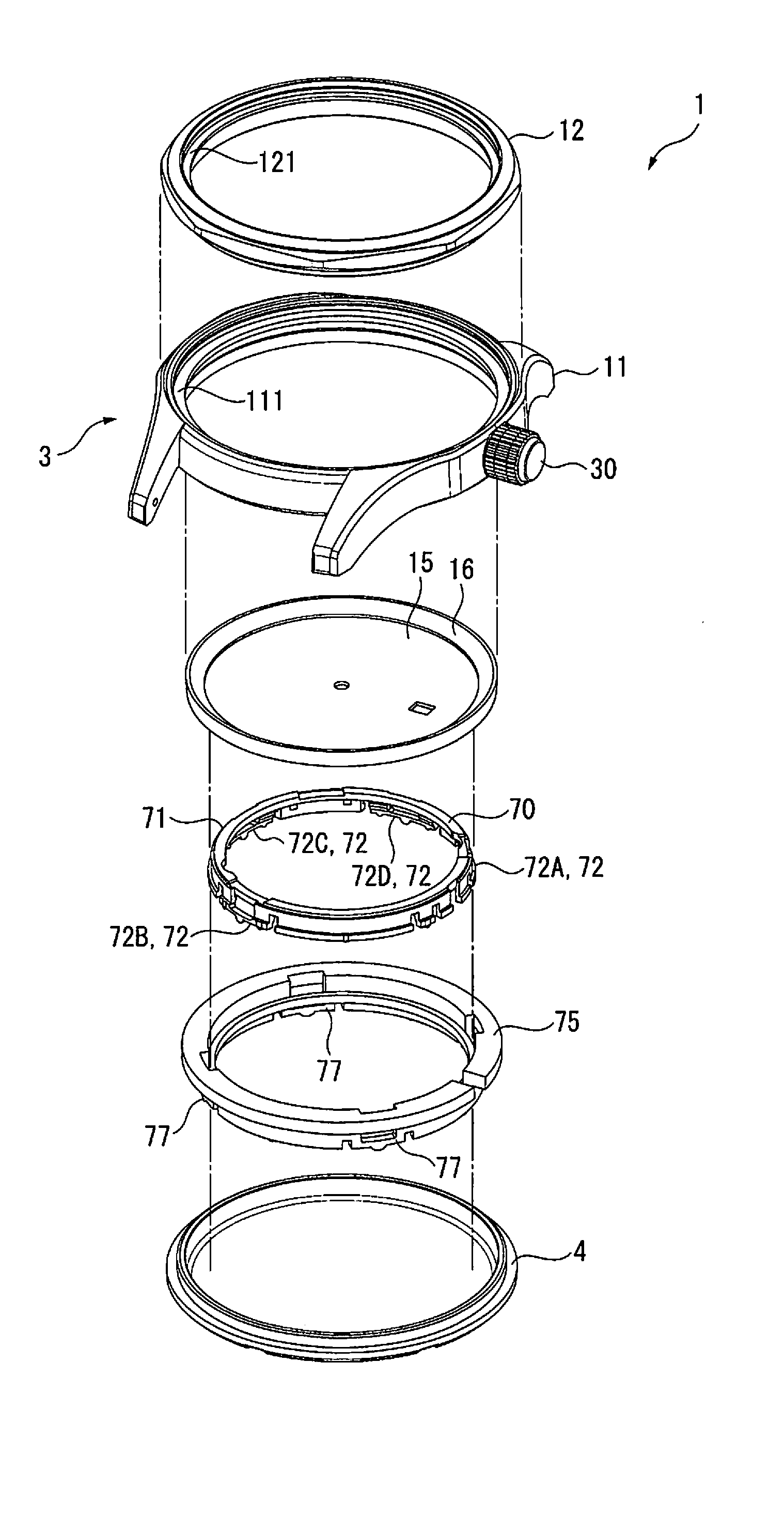
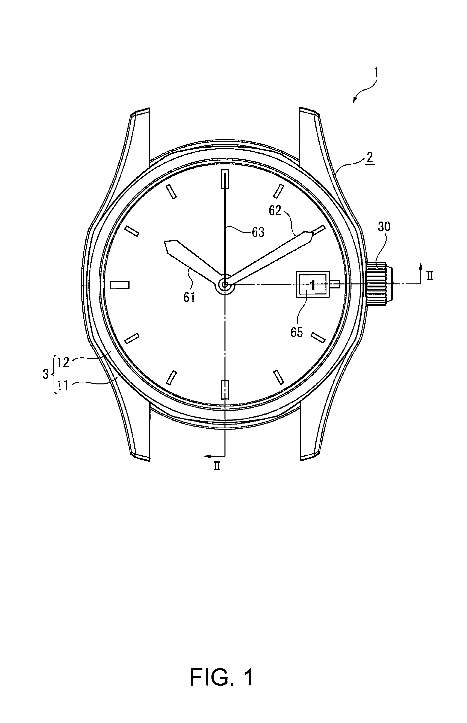
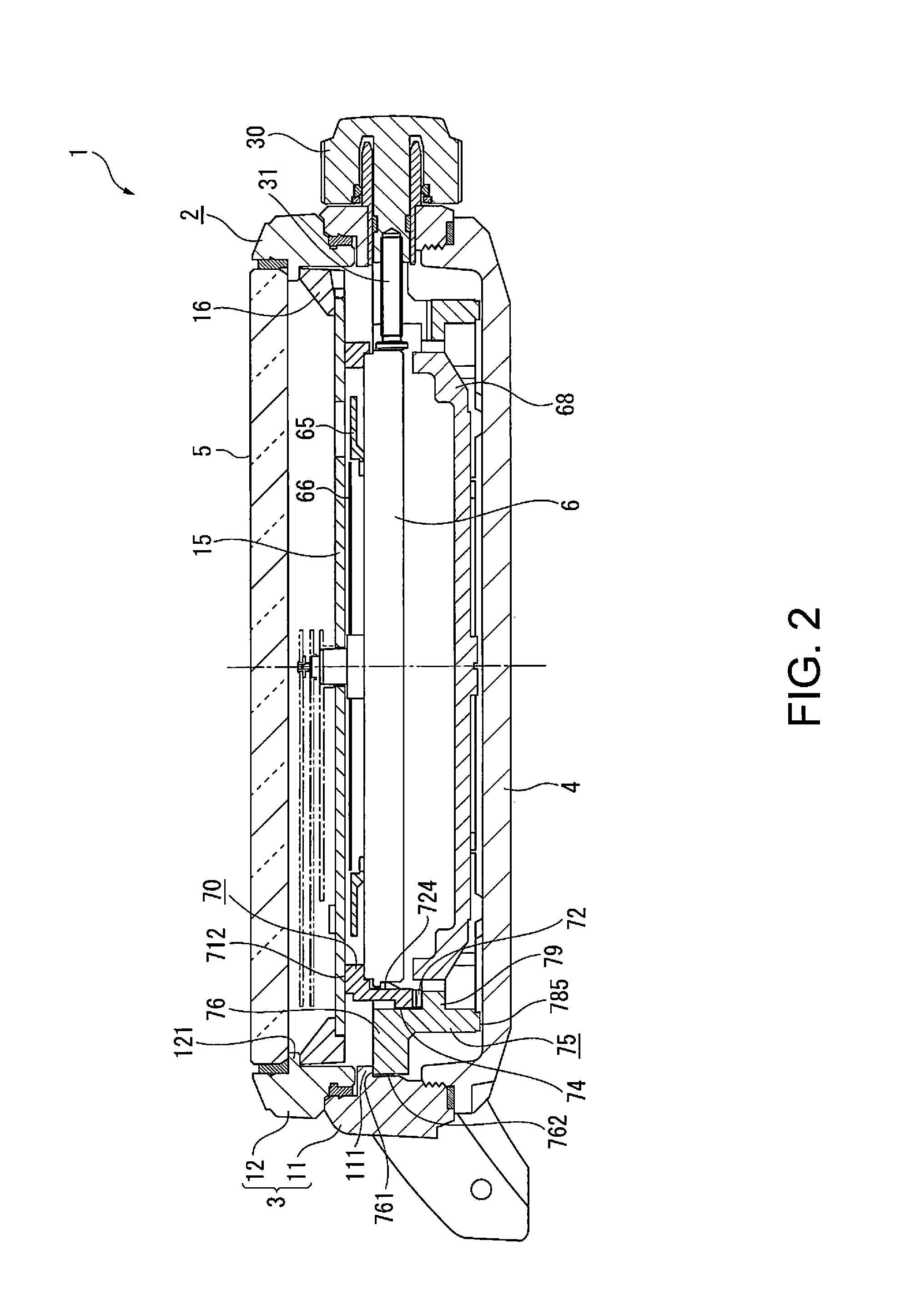
[0030]A timepiece (wristwatch) 1 according to an embodiment of the invention will be described below with reference to FIGS. 1 to 5. FIG. 2 is a cross-sectional view taken along the line II-II in FIG. 1. In FIG. 2, the left half shows a cross section of part of the timepiece, the portion from the six-o'clock position to the shaft of indicating hands, and the right half shows a cross section of part of the timepiece, the portion from the shaft of the indicating hands to the three-o'clock position. In the description of each component of the timepiece 1, the surface of the component on the side facing the front surface of the timepiece 1 (the side facing a cover glass plate 5) is called a front surface or an upper surface, and the surface of the component on the side facing a case back 4 is called a rear surface, a bottom surface, or a lower surface in some cases.

[0031]The timepiece 1 includes an exterior case 2, which accommodates a movement, which will be described later, and other ...


PUM


Abstract

A timepiece includes an exterior case having a protruding section, a case back, a dial receiving ring, a dial, a dial ring, and a casing ring disposed around the outer circumference of the dial receiving ring. The casing ring includes a casing-ring-side contact section that comes into contact with the inner circumferential surface of the exterior case, a front-surface-side contact section that comes into contact with the protruding section, a casing ring spring section that is formed to be elastically deformable in the thickness direction of the timepiece and comes into contact with the case back, and a support section that protrudes from the inner circumferential surface of the casing ring.

Description

BACKGROUND[0001]1. Technical Field[0002]The present invention relates to a timepiece.[0003]2. Related Art[0004]Wristwatches are so designed that a common movement, which is a basic component, is incorporated in a timepiece case that varies in terms of size and exterior appearance by using a casing ring for both cost reduction and an increase in exterior appearance variation, whereby a plurality of kinds of timepiece having different sizes and exterior appearances are configured (see JP-A-2001-13268, for example).[0005]In JP-A-2001-13268, the casing ring (support member) is positioned in the in-plane direction by allowing protrusions formed at a plurality of locations along the outer circumferential surface of the casing ring to come into contact with the inner circumferential surface of an exterior case.[0006]On the other hand, the casing ring is positioned in the thickness direction (height direction) of the timepiece by pressing the front surface of the periphery of a dial against...

Claims


Application Information

Patent Timeline
Patent Type & Authority Patents(United States)
IPC IPC(8): G04B37/04
CPCG04B37/04G04B37/0418G04B37/05G04B37/052
Inventor MOMOSE, TOMONORI
Owner SEIKO EPSON CORP
Why Eureka
Try Eureka