In-mold labeled container and molding process thereof

a labeling container and label technology, applied in the field of in-mold labeled containers, can solve the problems of negative effects on the appearance and touch feel of containers, discontent and inconvenience with labels, and the difficulty of applying labels firmly and stably, and achieves good shape, accurate determination, and high precision.

Active Publication Date: 2017-11-07
YOSHINO KOGYOSHO CO LTD
View PDF15 Cites 0 Cited by
  • Summary
  • Abstract
  • Description
  • Claims
  • Application Information

AI Technical Summary

Benefits of technology

The invention is a container with in-mold labels that are held in place by a split mold and fixed to the body of the container. The in-mold labels are held at right positions opposed to the body molding planes, ensuring a stable and strong attachment. The container has a high decorative effect and can also be used as reinforcing material for the body, allowing for thinner walls. Additionally, the invention allows for different displays of the in-mold labels for the upper and lower areas of the body, providing large changes in decorative displays.

Problems solved by technology

Moreover, these labels inevitably create slight unevenness or a step between the body surface and label edges, and this step may have negative effects on the container appearance and the feel of touch.
In addition, with a trend toward thin wall of the container body, there were discontent and inconvenience concerning labels because it becomes more and more difficult to apply labels firmly and stably to thin body wall.
In addition, the in-mold labels are given a light blocking effect or an oxygen barrier property so that the container can block the light or does not allow oxygen to pass through the body wall.

Method used


Image

  • In-mold labeled container and molding process thereof
  • In-mold labeled container and molding process thereof
  • In-mold labeled container and molding process thereof

Examples


first embodiment

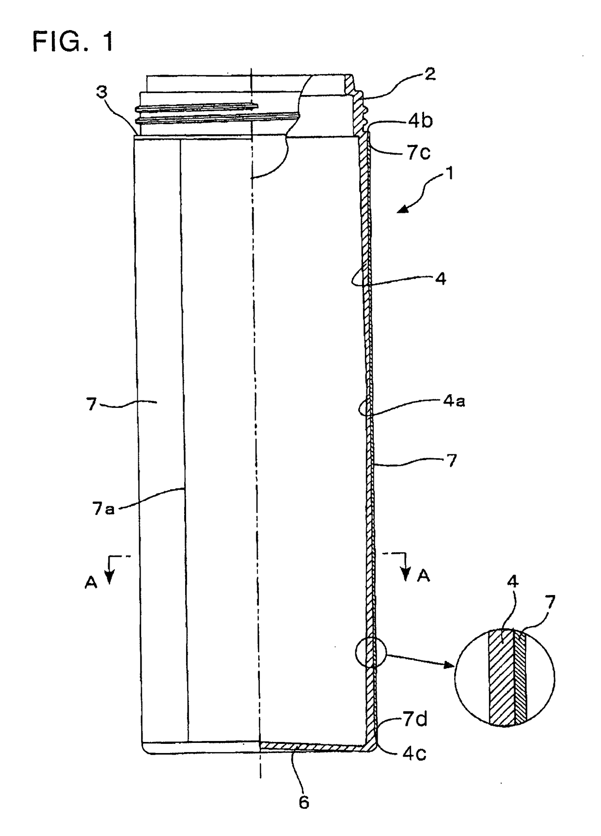
[0082]FIG. 1 is a front elevational view of the container in this invention, with the right half shown in a vertical section. This container comprises a main container 1, which is a blow molded product made of a synthetic resin, and in-mold labels 7 clad around, and fixed to, outer surface of a body 4 of the main container 1. This main container 1 comprises the cylindrical body 4 in the shape of a straight cylinder, a bottom 6 dented slightly inward in a spherical arc to close the body 4, a shoulder 3 which is an inward step from upper end of the body 4, and a cylindrical neck 2 having a diameter shorter than that of the body 4 and also having a screw thread notched around the outer surface.

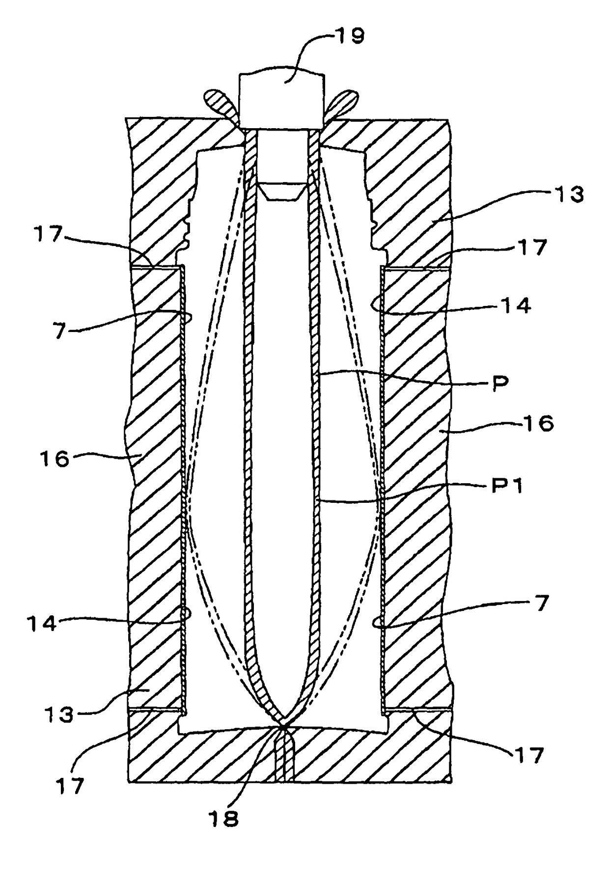
[0083]In the first embodiment of this invention, the body 4 of the main container 1 is disposed between the shoulder 3 and the bottom 6, and comprises a thinnest wall portion 4a and other portions. The thinnest wall portion 4a is the first to come in contact with the body molding planes 14 of a s...

second embodiment

[0090]In this second embodiment, the container has a stable shape-retaining ability because the peripheral raised ribs 5 serve as reinforcing ribs. The peripheral raised ribs 5 have the largest outer diameter, as compared to other portions of the main container 1, and stabilize the container posture when many containers stand side by side. As a result, the containers can be handled in good conditions during storage or transportation. During the time when the containers are handled, the ribs protect the in-mold labels 7 fixed to outer surface of the body so that the labels 7 may not by accident come in contact with other containers or objects.

[0091]The cap 8 is fitted to the container in the second embodiment of this invention so that the container is utilized as a caster. This cap 8 comprises a fitting cylinder 9 which is fitted around the neck 2 by screw engagement, a top plate 10 disposed at the upper end of the fitting cylinder 9 to close roughly a half of the upper opening, and ...

third embodiment

[0094]In the case of the third embodiment, the thinnest wall portion 4a is in the position opposed to the in-mold labels 7. A combination of the main container 1 and the in-mold labels 7 creates a decorative effect on the container.

[0095]FIG. 6 shows the container in the fourth embodiment of this invention, in which the in-mold labels 7 are fixed to the body 4, excluding the upper end portion connected to the shoulder 3 and the lower end portion connected to the bottom 6, but are disposed separately in an upper area and a lower area of the body 4 with no labeled area in between. Other than this configuration, the container has the same construction as the first embodiment.


PUM

PropertyMeasurementUnit
lengthaaaaaaaaaa
sizeaaaaaaaaaa
half-lengthaaaaaaaaaa

Abstract

The objects of this invention are to set a predetermined height position for the portion of parison or preform that is the first to come in contact with body molding planes of a split mold and to prevent air from being trapped between in-mold labels and the container which is blow molded from the parison or the preform. In-mold labels are fixed to the entire outer surface of body of main container. An annular thinnest wall portion is formed in the wall of the body so that the thinnest wall portion is the first to come in contact with the body molding planes of a split mold. Under this construction, no bulge of air is formed between the body and the in-mold labels fixed to the entire surface of the body.

Description

[0001]This is a Divisional of U.S. application Ser. No. 11 / 989,613 filed May 7, 2009, which is a National Phase of International Application No. PCT / JP2006 / 312235 filed Jun. 19, 2006, which claims the benefit of Japanese Application No. 2005-221841 filed Jul. 29, 2005. The disclosure of the prior applications is hereby incorporated by reference herein in its entirety.TECHNICAL FIELD[0002]This invention relates to an in-mold labeled container having in-mold labels firmly fixed to an outer peripheral surface of a body in a manner extending around the body over a whole circumferential length, and to a molding process thereof,BACKGROUND ART[0003]As a means of applying a label bearing a decorative pattern, a product name, and / or instructions onto the surface of a blow molded synthetic resin container, there are many types of labels on which decorative patterns, product names, and / or instructions are printed, and which are glued on the body surfaces of the containers.[0004]These labels to...

Claims


Application Information

Patent Timeline
Patent Type & Authority Patents(United States)
IPC IPC(8): B29C49/24B29C49/00B65D23/08B29C49/48B29C49/06B29C49/04B29K101/00B29K105/00B29L31/00
CPCB29C49/24B29C49/0078B29C49/2408B29C49/4817B65D23/0864B29B2911/14326B29L2031/712B29C49/06B29C2049/2412B29C2049/2472B29K2101/00B29K2105/256B29C49/04B29C2949/072B29C2949/0715B65D1/40B65D23/08B29C2949/074
Inventor MOTEGI, TAKAYUKIISHIYAMA, SHINICHIKUROSAWA, TAKAOSHIMIZU, YASUYUKI
Owner YOSHINO KOGYOSHO CO LTD
Why Eureka
Try Eureka