System for repairing an anatomical canal by means of an implant with a progressive opening

Inactive Publication Date: 2001-10-16
B BRAUN CELSA
View PDF8 Cites 182 Cited by
  • Summary
  • Abstract
  • Description
  • Claims
  • Application Information

AI Technical Summary

Benefits of technology

is to propose a solution making possible in particular to control the installation conditions with regard to the moment when the tubular bod

Problems solved by technology

Moreover, other threads or filaments are associated with the release and retaining means already m

Method used


Image

  • System for repairing an anatomical canal by means of an implant with a progressive opening
  • System for repairing an anatomical canal by means of an implant with a progressive opening
  • System for repairing an anatomical canal by means of an implant with a progressive opening

Examples


Embodiment Construction

will now be provided with reference to the accompanying drawings, in which:

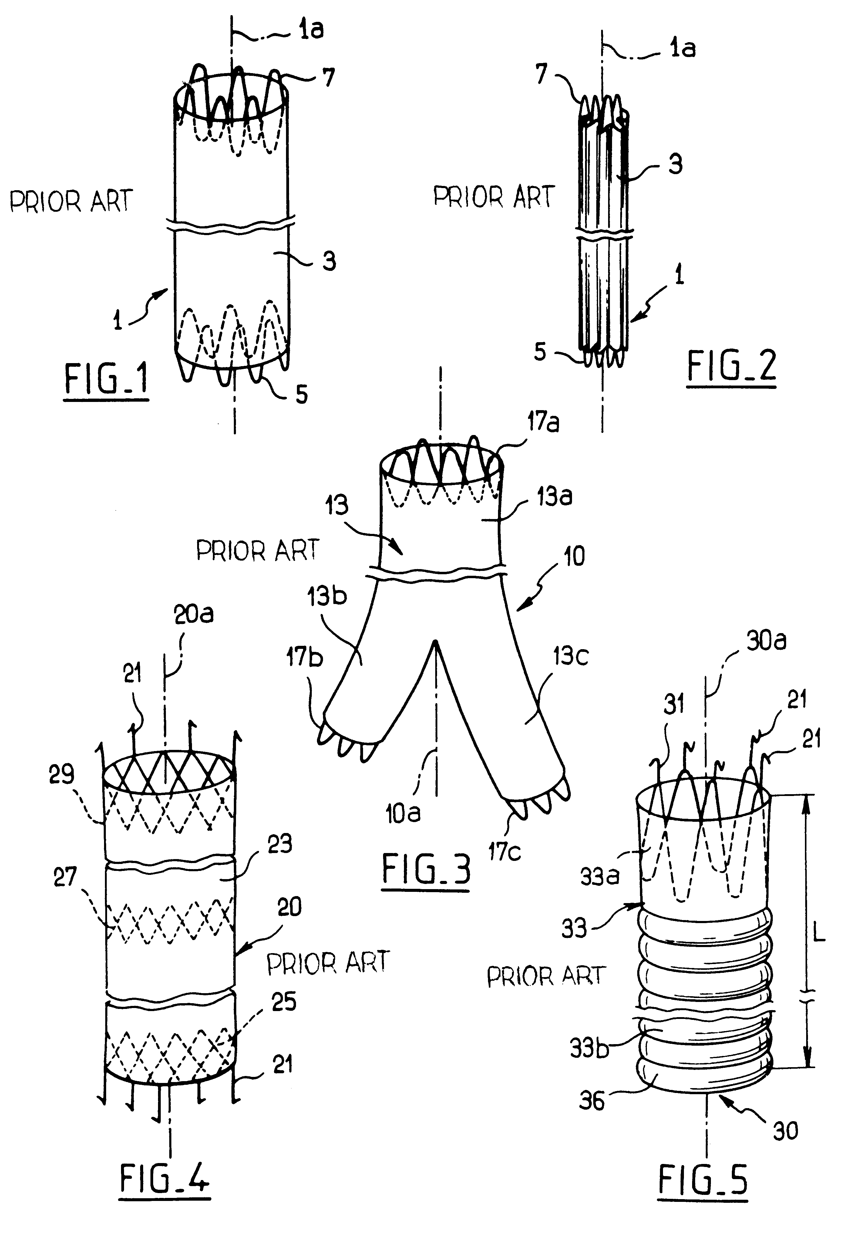
FIGS. 1 to 5 show diagrammatically alternative various prior art vascular implants.

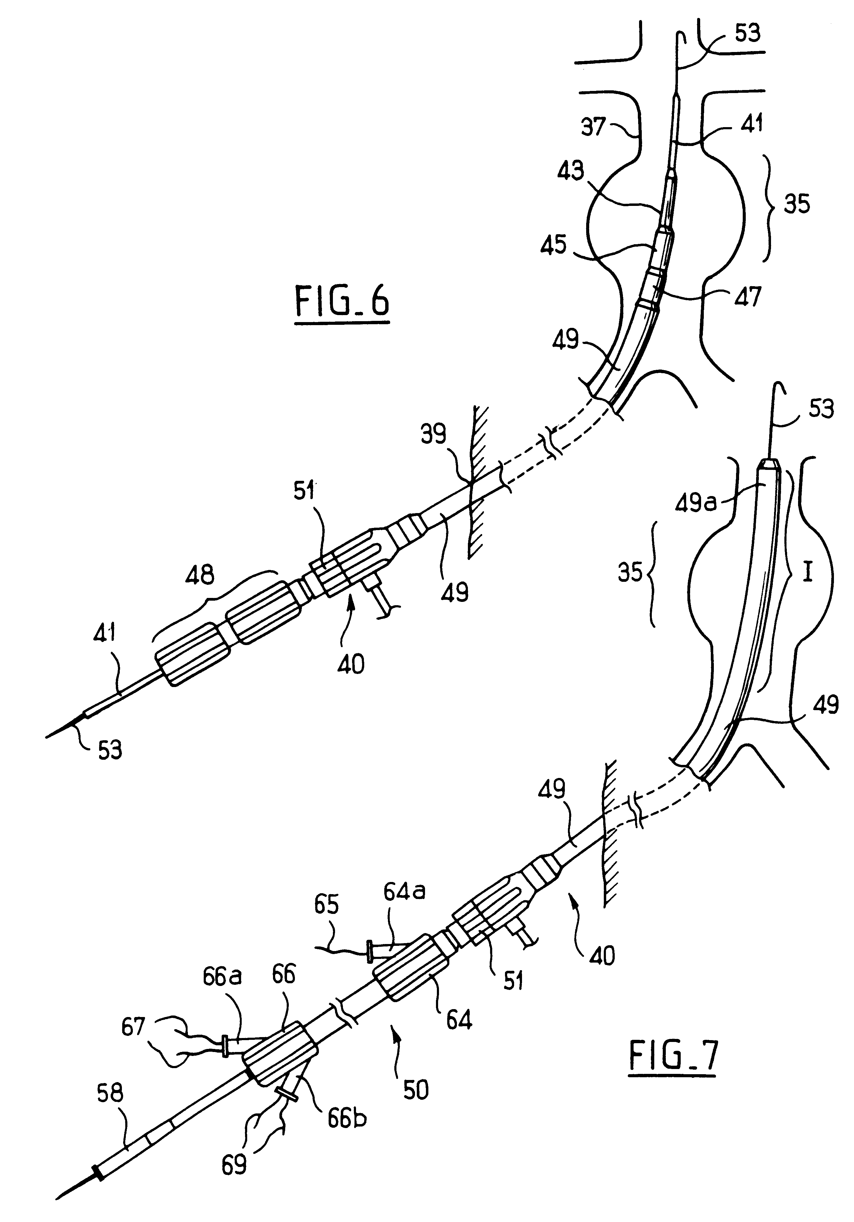
FIGS. 6, 7, 8, 9 and 13 essentially show an implantation device that can be used to introduce one of the above implants into its implantation canal, FIGS. 7 and 13 illustrating the device in place and showing the ties that are characteristic of the invention,

FIG. 9 is an enlarged detail view of FIG. 8, at the point identified by IX in FIG. 8, and shows the flexible threads which are characteristic of the invention,

FIG. 10 is an even more enlarged view of the upper part in FIG. 9,

FIGS. 11 and 12 show (in an enlarged detail view in the case of FIG. 12) the lacing or knotting principle employed for the body of the implant in FIGS. 9 and 10, which is a characteristic of the invention,

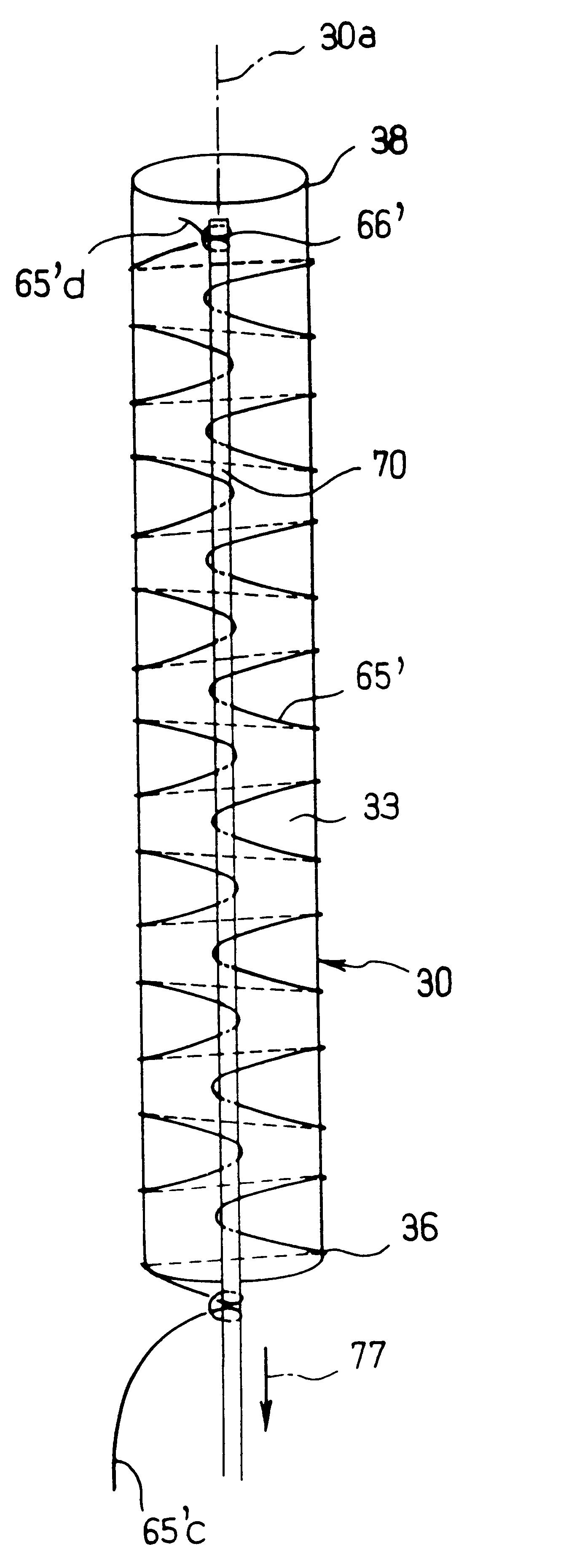
FIG. 14 shows the implant in place in its receiving canal,

FIGS. 15 and 16 show (in an enlarged detail view in the case of FIG. 16) an alternative form...


PUM


Abstract

The system-for repairing an anatomic duct comprises an implant having a tubular body adapted to be radially expanded, once the implant is arranged in the duct and also a device for installing the implant in said duct. The device comprises a tie for maintaining the body in a restricted configuration, for the implantation thereof in the duct, and means for releasing the tie in order to allow the implant to radially expand.

Description

The invention concerns a system or device for repairing an anatomical canal, or duct, in which a fluid circulates.In particular, it is a matter of repairing a blood vessel.DESCRIPTION OF THE BACKGROUND ARTThe vessel "to be repaired" may typically be affected by one or more aneurisms or by degeneration necessitating the installation of tubing intended to channel the blood in the damaged portion(s), thus preventing the blood pressure from being allowed to be applied to the weakened walls of the vessel.Up to the present, numerous vascular implants for the treatment of aneurisms have been proposed.For several years, the installation of these implants by the percutaneous endoluminal route has been favoured.Among these existing systems, WO-A-96 / 18361 proposes in particular a system comprising:an implant having a body suitable for channelling the fluid in question along a single or branched tube extending generally along a major axis of the implant, at least in one configuration of the lat...

Claims


Application Information

Patent Timeline
IPC IPC(8): A61F2/06A61F2/95A61F2/962
CPCA61F2/962A61F2002/9511A61F2/95
Inventor NADAL, GUY
Owner B BRAUN CELSA
Why Eureka
Try Eureka