Circulatory assistance system

Inactive Publication Date: 2019-11-28
ASSOC MARIE LANNELONGUE
View PDF0 Cites 0 Cited by
  • Summary
  • Abstract
  • Description
  • Claims
  • Application Information

AI Technical Summary

Benefits of technology

[0013]An object of the invention is therefore to propose a circulatory assistance system implantable into a living being limiting the risks of hemolysis of blood and th

Problems solved by technology

1 to 10% of these patients suffer from an advanced form called “terminal” form where the heart is no longer sufficient to ensure the circulatory function of the body and leads to a multiple organ dysfunction.
Medical treatments represent then only a palliative therapeutic option while curative treatments are limited.
However, it cannot meet the needs of this population due to lack of a sufficient number o

Method used


Image

  • Circulatory assistance system
  • Circulatory assistance system
  • Circulatory assistance system

Examples


Embodiment Construction

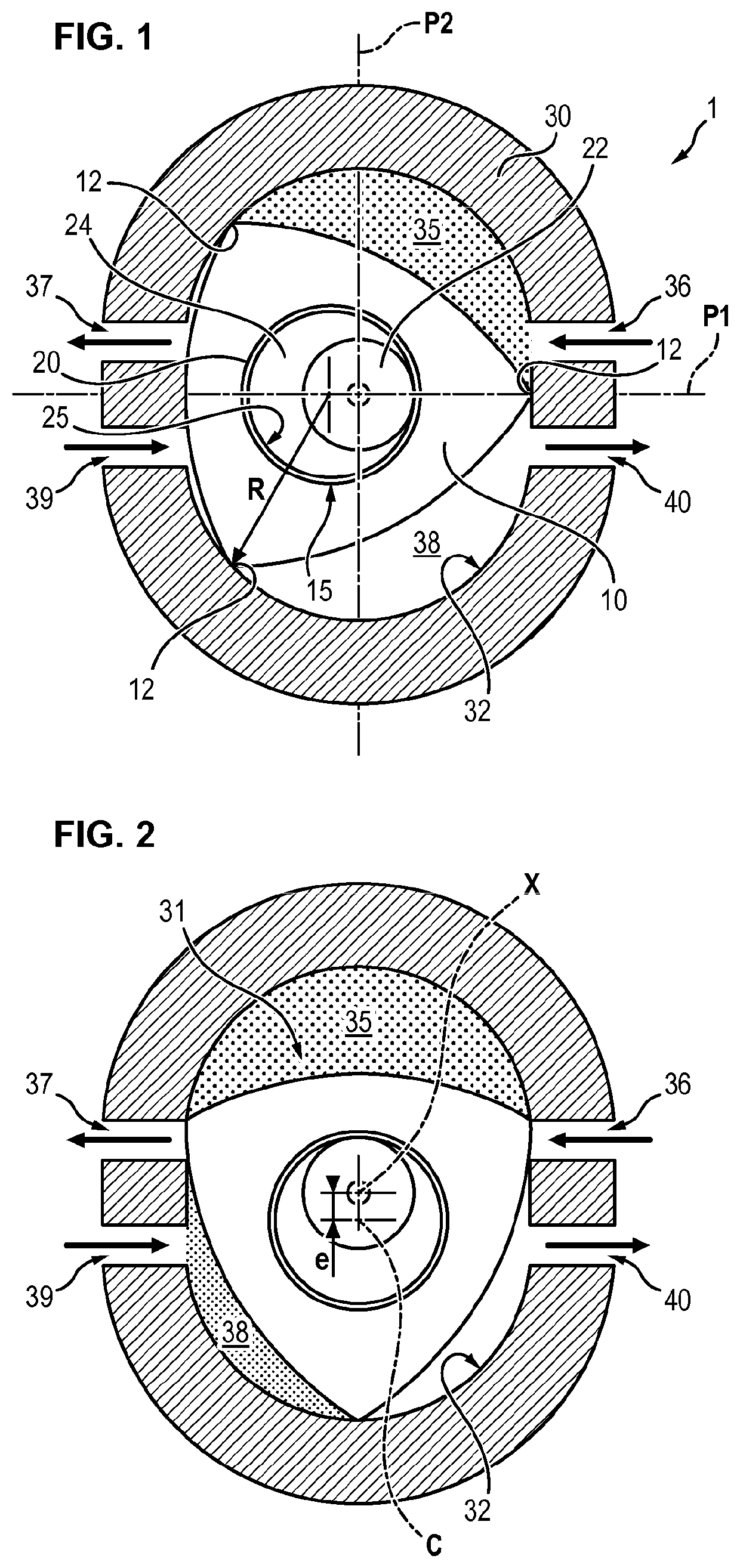
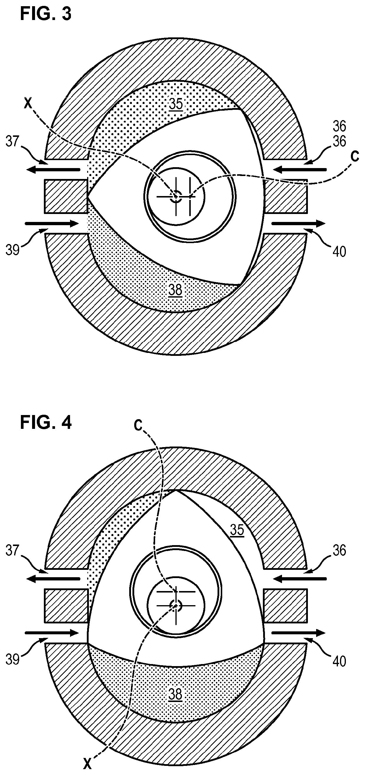
[0046]A circulatory assistance system 1 according to the invention comprises a rotor 10, a camshaft 20 and a stator 30.

[0047]The rotor 10 comprises an outer surface defining a curve having the shape of a Reuleaux triangle, and a housing delimited by inner walls.

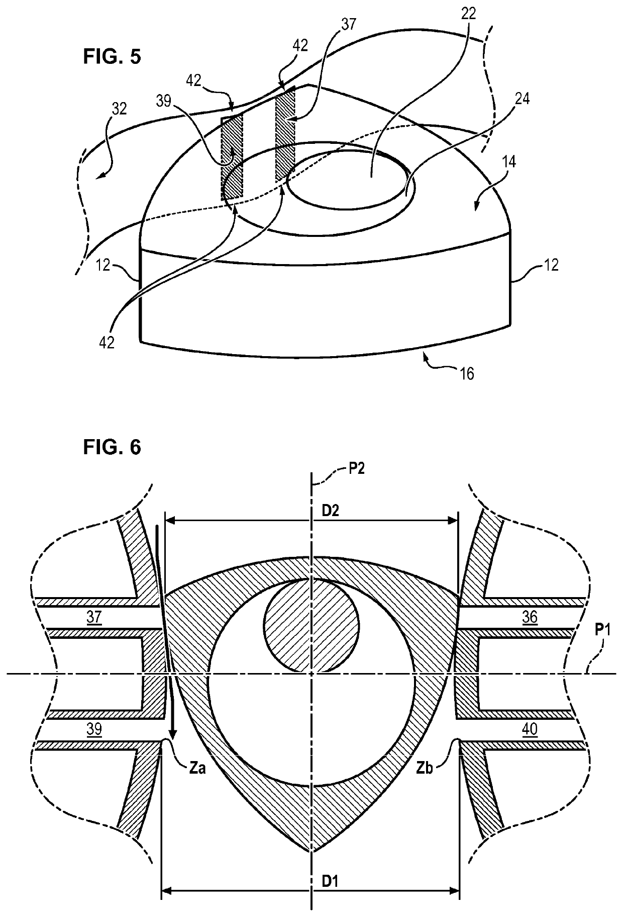
[0048]The Reuleaux triangle is a curve of constant width, i.e. a curve all of whose diameters have the same length. More precisely, the Reuleaux triangle is a closed plane curve whose width, measured by the distance between two opposite parallel straight lines tangent thereto, is the same whatever the orientation of these straight lines. The rotor 10 thus has three apexes 12 corresponding to the vertices of the Reuleaux triangle separated by three curved surfaces. There is also meant by radius R of the rotor 10, the distance between the center of symmetry of the rotor 10 and an apex 12 of the rotor 10.

[0049]The camshaft 20 comprises a central shaft 22 on which a cam 24 is securely fixed. The camshaft 20 is housed in the housi...


PUM


Abstract

The invention relates to a circulatory assistance system comprising: a rotor in the shape of a Reuleaux triangle; and a camshaft received in a housing of the rotor and designed to rotate the rotor about an axis of rotation. The inner walls of the housing of the rotor are in contact at all points with the outer surface of the cam such that the assembly formed by the cam and the rotor does not have a clearance volume.

Description

FIELD OF THE INVENTION[0001]The invention relates to the field of implantable prostheses, and more particularly of circulatory assistance systems such as heart pumps.TECHNOLOGICAL BACKGROUND[0002]Heart failure is a major public health problem in developed countries to the point of affecting approximately 5.7 million Americans with an incidence of 670,000 patients a year. Its impact in terms of morbidity and mortality is estimated at 300,000 deaths and 2.4-3.5 million hospitalizations per year.[0003]1 to 10% of these patients suffer from an advanced form called “terminal” form where the heart is no longer sufficient to ensure the circulatory function of the body and leads to a multiple organ dysfunction. Medical treatments represent then only a palliative therapeutic option while curative treatments are limited.[0004]Nowadays, the reference treatment is the heart transplantation. However, it cannot meet the needs of this population due to lack of a sufficient number of organ donors. ...

Claims


Application Information

Patent Timeline
IPC IPC(8): A61M1/10A61M1/12F01C13/04F04C18/22
CPCF04C18/22A61M1/1012F01C13/04A61M1/122A61M60/562A61M60/441A61M60/122A61M60/253A61M60/258A61M60/148A61M60/205
Inventor ISORNI, MARC-ANTOINE
Owner ASSOC MARIE LANNELONGUE
Why Eureka
Try Eureka