Ignition coil for an internal combustion engine

a technology for internal combustion engines and ignition coils, which is applied in the direction of transformers/inductances magnetic cores, mechanical devices, machines/engines, etc., can solve the problems of insufficient use of sole use to balance the requirements of miniaturization and high-energy output, conventional technology was not able to raise, and the high-level of miniaturization was not achieved

Inactive Publication Date: 2002-03-05
DENSO CORP
View PDF39 Cites 9 Cited by
  • Summary
  • Abstract
  • Description
  • Claims
  • Application Information

AI Technical Summary

Problems solved by technology

In this way, the use of bias magnets has been proposed in the prior art but their sole use is not enough to balance both requirements for miniaturization and high-energy output.
However, conventional technol

Method used


Image

  • Ignition coil for an internal combustion engine
  • Ignition coil for an internal combustion engine
  • Ignition coil for an internal combustion engine

Examples


Embodiment Construction

Preferred embodiments of the present invention are described hereinafter with reference to the accompanying drawings.

An embodiment of an ignition coil for an internal combustion engine according to the present invention is explained using FIGS. 1-25.

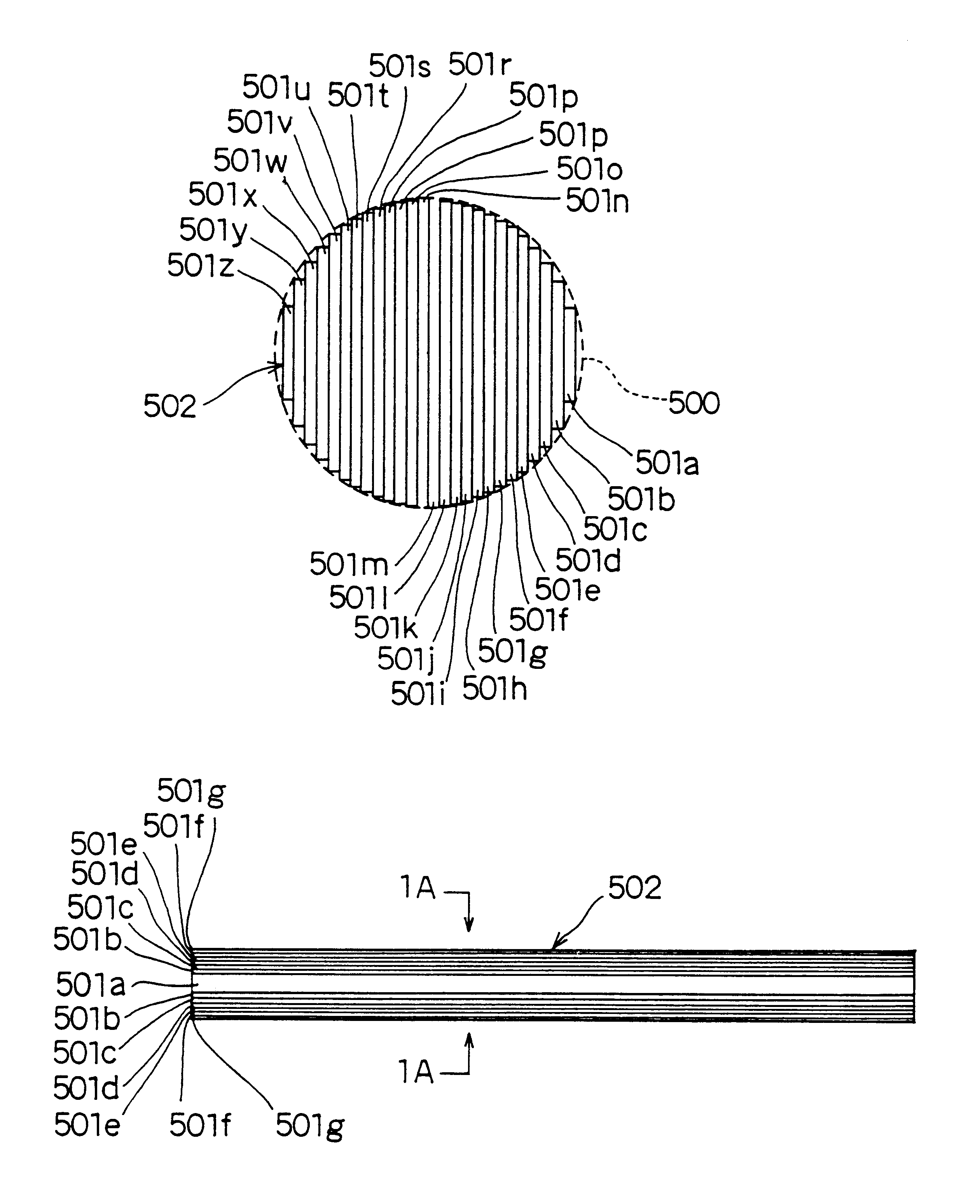
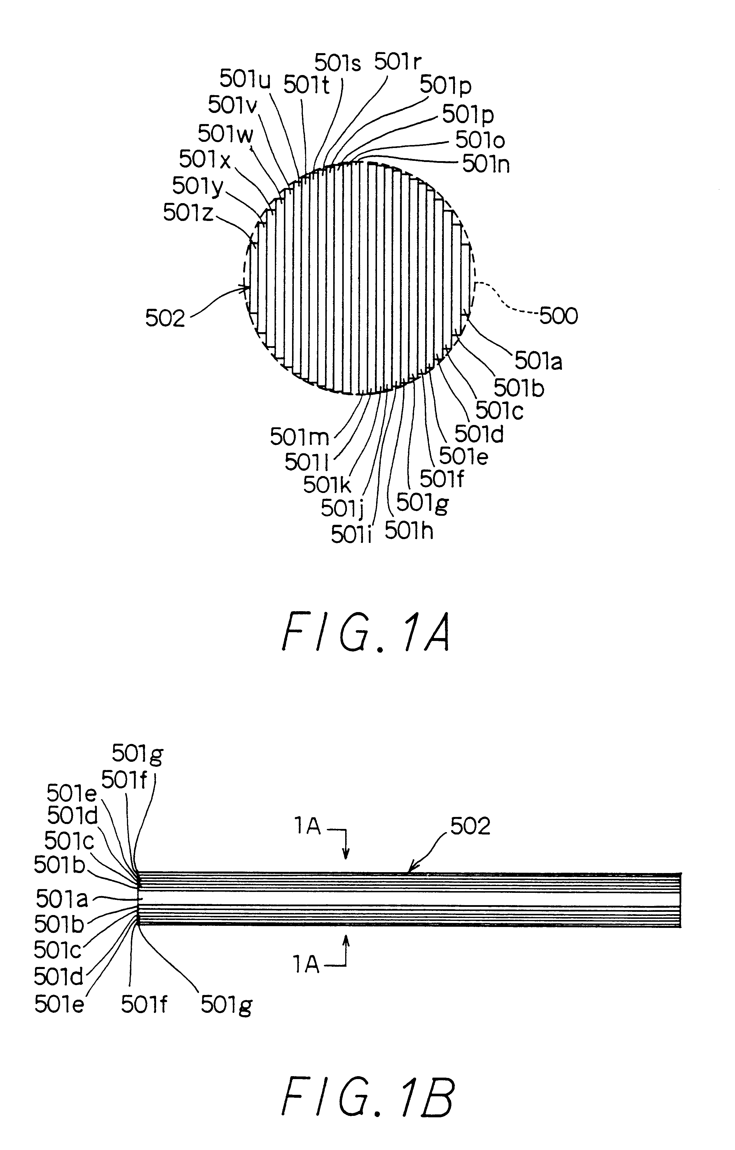
FIGS. 1A and 1B show flat and side views of a core (referred to as iron core hereinafter) 502 flat and side views. This iron core 502 is used in a transformer 5 part of an ignition coil 2 shown in FIG. 2.

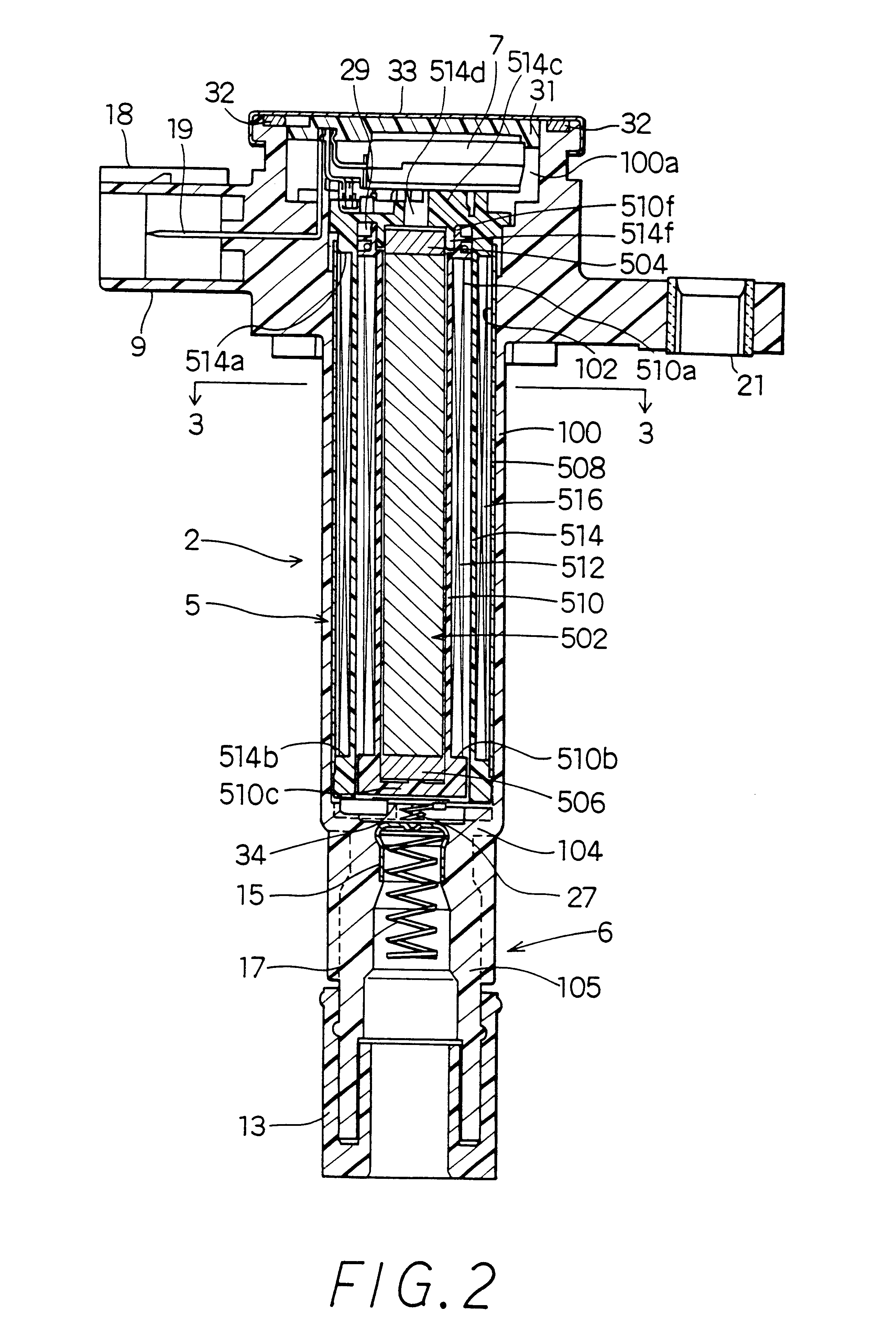
As shown in FIGS. 2 and 3, the ignition coil 2 for an internal combustion engine is mainly made up of a cylindrical transformer part 5, a control circuit part 7 positioned at one end of this transformer part 5 which interrupts a primary current of the transformer part 5, and a connecting part 6 positioned at the other end of the transformer part 5 which supplies a secondary voltage produced in the transformer part 5 to an ignition plug (not shown).

The ignition coil 2 has a cylindrical case 100 made of a resin material. This case 100 has ...


PUM


Abstract

An ignition coil for an internal combustion engine is mainly made up of a transformer part and a control circuit part and a connecting part, and the transformer part is made up of a iron core which forms an open magnetic path, magnets, a secondary spool, a secondary coil, a primary spool and a primary coil. By respectively setting the cross-sectional area SC of the iron core between 39 to 54 mm2, the ratio of the cross-sectional area SM of the magnets with the cross-sectional area SC of the iron core in the 0.7 to 1.4 range, the ratio of the axial direction length Lc of the iron core with the winding width L of the primary and secondary coils in the 0.9 to 1.2 range, and the winding width L in the 50 to 90 mm range, the primary energy produced in the primary coil can be increased without increasing the external diameter A of the case.

Description

This application is related to and claims priority from Japanese Patent Application Nos. Hei-6-306380, Hei-6-302298 and Hei-7-141933, the contents of which are hereby incorporated by reference.1. Field of the InventionThe present invention relates to an ignition coil for an internal combustion engine. More specifically, the present invention relates to an ignition coil for an internal combustion engine having an open magnetic path structure.2. Description of Related ArtConventionally, there are many known forms of ignition coils which supply high voltages to ignition plugs of internal combustion engines.For example, Japanese Patent Laid Open Publication Nos. Hei-3-154311, Hei-2-228009 and Hei-3-13621 propose a cylindrical ignition coil.This type of ignition coil should be containable in a plug hole of the internal combustion engine. Therefore, in order to provide powerful ignition sparks to the ignition plug, the ignition coil must be able to generate enough energy while having a sm...

Claims


Application Information

Patent Timeline
IPC IPC(8): H01F38/00H01F38/12H01F27/245
CPCH01F27/245H01F38/12F02B2275/18H01F2038/125H01F2038/122F02P3/02
Inventor OOSUKA, KAZUTOYOKOJIMA, MASAMIKAWANO, KEISUKE
Owner DENSO CORP
Why Eureka
Try Eureka