Ignition coil for an internal combustion engine

a technology for internal combustion engines and ignition coils, which is applied in the direction of transformers/inductances magnetic cores, mechanical devices, machines/engines, etc., can solve the problems of insufficient use of sole use to balance the requirements of miniaturization and high-energy output, conventional technology was not able to raise, and the high-level of miniaturization was not achieved

Inactive Publication Date: 2002-05-16
DENSO CORP
View PDF0 Cites 1 Cited by
  • Summary
  • Abstract
  • Description
  • Claims
  • Application Information

AI Technical Summary

Benefits of technology

[0014] In this way, when this core is contained in a bobbin having inner contours which correspond to the circumscribing circle, the space that is wasted is reduce to no more than 10%. Thus, the electric voltage conversion efficiency between the coils wound up around the outer periphery of the bobbin can be improved. Also, by shaping the core to be inserted into the bobbin, the metal sheets can thus be held together by just inserting a cylinder stopper whose diameter is slightly smaller than that of the circumscribing circle without no need for fixing by pressing or the like. Thus, movement of the stacked magnetic sheets in the diametrical direction is prevented. Therefore, costs are lowered because there is no need for expensive press molds and the like.
[0027] In this way, because the ratio of the axial length L.sub.c of the magnetic path constituting member and the winding width L over which the coil is wound is set to L.sub.c / L.gtoreq.0.9, the magnets disposed on the two ends of the magnetic path constituting member do not greatly enter the range of the coil winding width L and reduction of the effective flux of the coil due to the diamagnetic field of the magnets is suppressed, and because L.sub.c / L is set to L.sub.c / L.ltoreq.1.2 the spacing of the magnets does not become too wide with respect to the coil winding width L and the magnets can be positioned on the two ends of the magnetic path constituting member in the range wherein a magnet bias flux acts well. Also, it is possible to further increase the electrical energy produced in the coil without increasing the case external diameter. As a result, since in correspondence with the secondary energy amount which the internal combustion engine demands, the external diameter of the case can be set smaller than for example 24 mm, and the necessary number of magnets can be one or a construction that does not use any magnets can also be adopted and in doing so, a cheap ignition coil can be provided for an internal combustion engine.

Problems solved by technology

In this way, the use of bias magnets has been proposed in the prior art but their sole use is not enough to balance both requirements for miniaturization and high-energy output.
However, conventional technology was not able to raise the ratio of the area covered by the iron core with the area provided for it (referred to as occupation rate hereinafter) and thus, a high-level of miniaturization was not achieved.

Method used


Image

  • Ignition coil for an internal combustion engine
  • Ignition coil for an internal combustion engine
  • Ignition coil for an internal combustion engine

Examples


Embodiment Construction

[0060] Preferred embodiments of the present invention are described hereinafter with reference to the accompanying drawings.

[0061] An embodiment of an ignition coil for an internal combustion engine according to the present invention is explained using FIGS. 1-25.

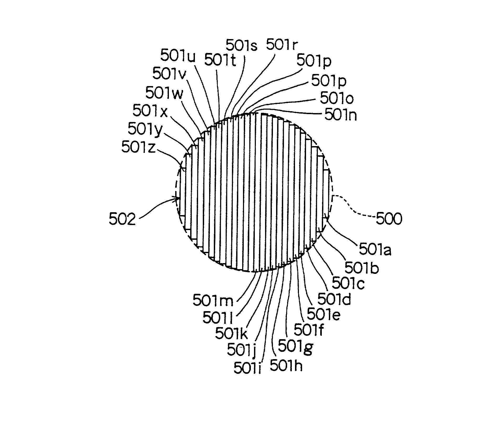
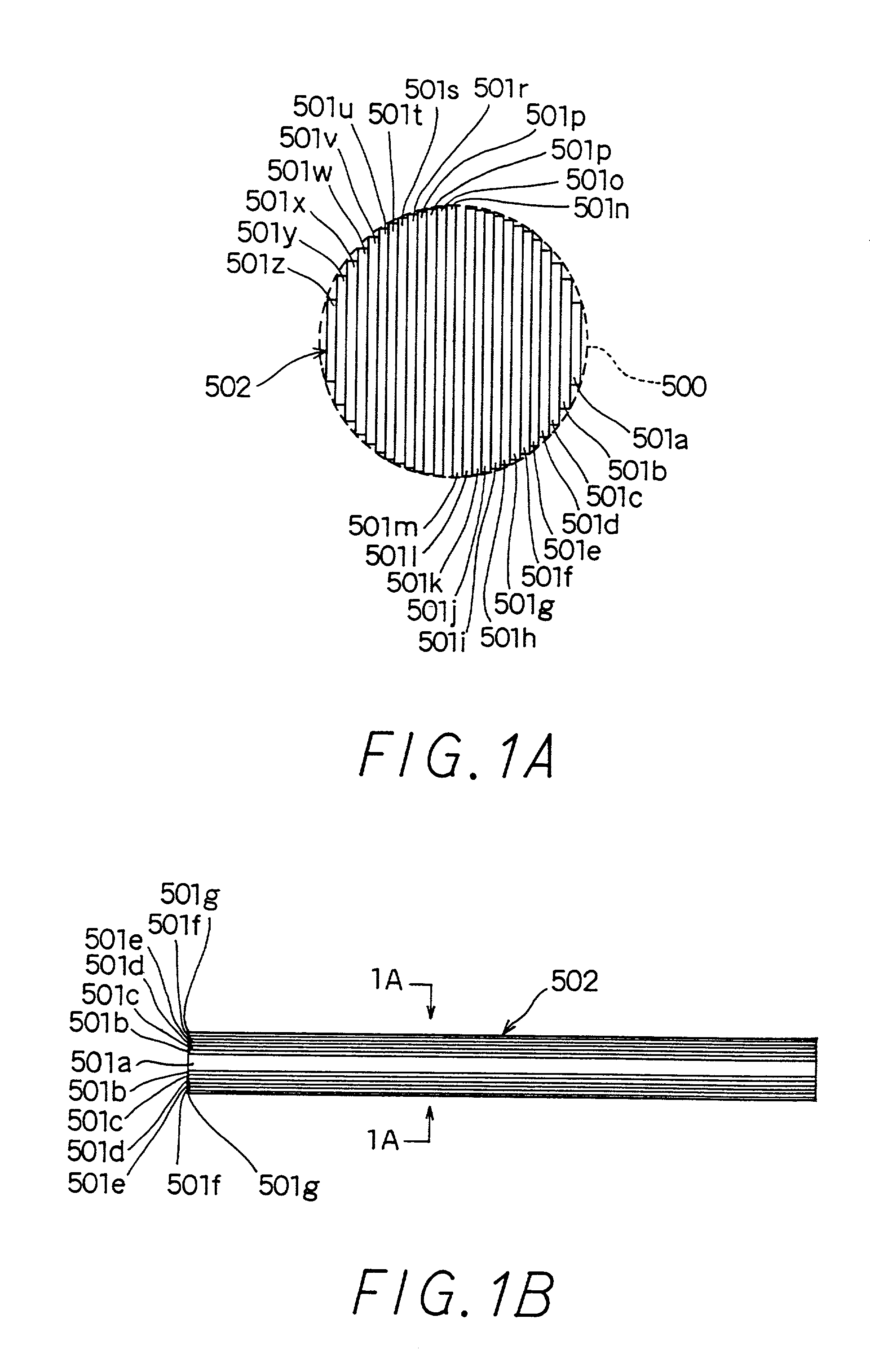
[0062] FIGS. 1A and 1B show flat and side views of a core (referred to as iron core hereinafter) 502 flat and side views. This iron core 502 is used in a transformer 5 part of an ignition coil 2 shown in FIG. 2.

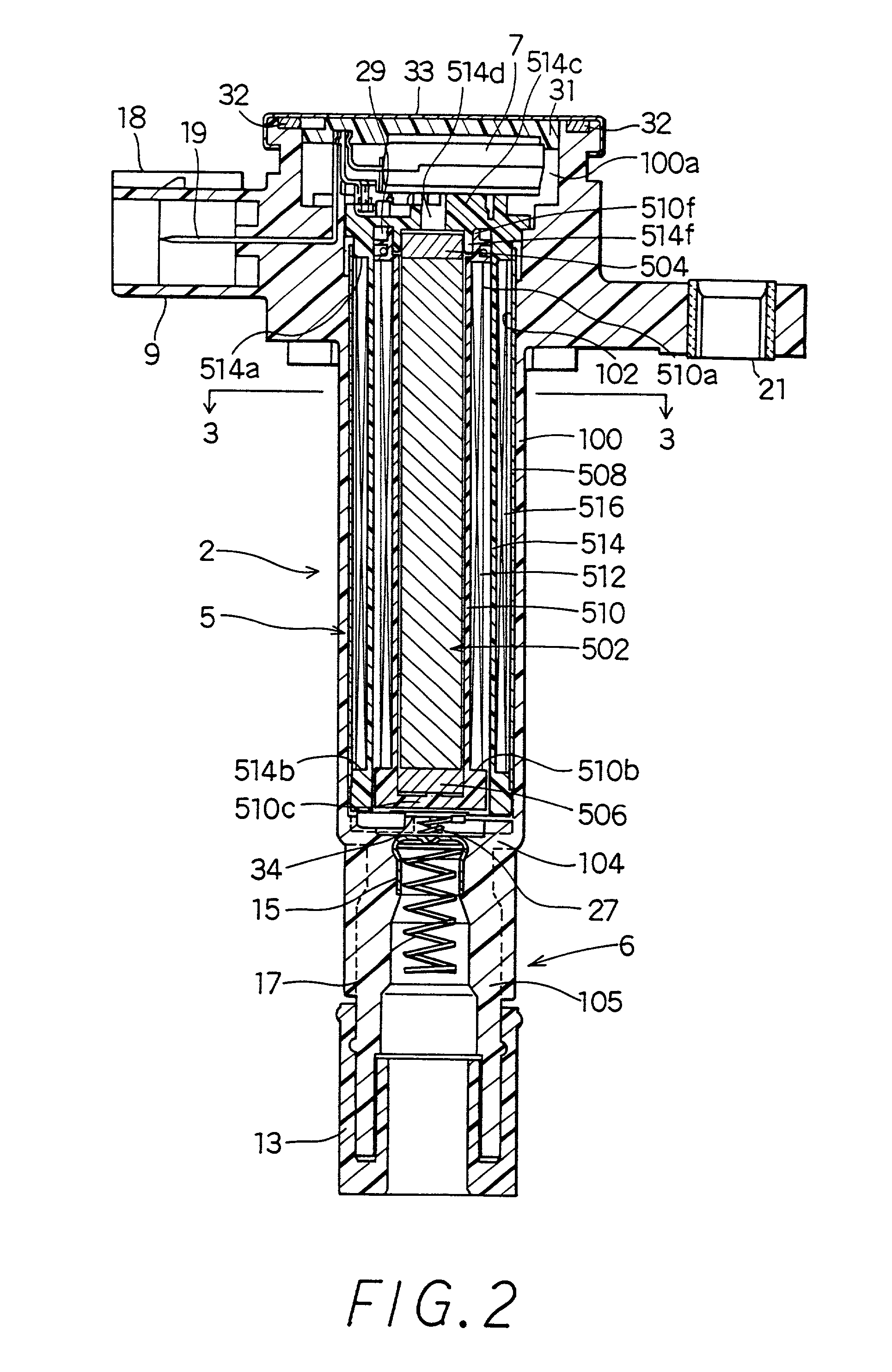
[0063] As shown in FIGS. 2 and 3, the ignition coil 2 for an internal combustion engine is mainly made up of a cylindrical transformer part 5, a control circuit part 7 positioned at one end of this transformer part 5 which interrupts a primary current of the transformer part 5, and a connecting part 6 positioned at the other end of the transformer part 5 which supplies a secondary voltage produced in the transformer part 5 to an ignition plug (not shown).

[0064] The ignition coil 2 has a cylindrical case 100 made of a...


PUM

PropertyMeasurementUnit
diameteraaaaaaaaaa
thicknessaaaaaaaaaa
diameteraaaaaaaaaa

Abstract

An ignition coil for an internal combustion engine is mainly made up of a transformer part and a control circuit part and a connecting part, and the transformer part is made up of a iron core which forms an open magnetic path, magnets, a secondary spool, a secondary coil, a primary spool and a primary coil. By respectively setting the cross-sectional area SC of the iron core between 39 to 54 mm2, the ratio of the cross-sectional area SM of the magnets with the cross-sectional area SC of the iron core in the 0.7 to 1.4 range, the ratio of the axial direction length LC of the iron core with the winding width L of the primary and secondary coils in the 0.9 to 1.2 range, and the winding width L in the 50 to 90 mm range, the primary energy produced in the primary coil can be increased without increasing the external diameter A of the case.

Description

[0001] This application is related to and claims priority from Japanese Patent Application Nos. Hei-6-306380, Hei-6-302298 and Hei-7-141933, the contents of which are hereby incorporated by reference.[0002] 1. Field of the Invention[0003] The present invention relates to an ignition coil for an internal combustion engine. More specifically, the present invention relates to an ignition coil for an internal combustion engine having an open magnetic path structure.[0004] 2. Description of Related Art[0005] Conventionally, there are many known forms of ignition coils which supply high voltages to ignition plugs of internal combustion engines.[0006] For example, Japanese Patent Laid Open Publication Nos. Hei-3-154311, Hei-2-228009 and Hei-3-13621 propose a cylindrical ignition coil.[0007] This type of ignition coil should be containable in a plug hole of the internal combustion engine. Therefore, in order to provide powerful ignition sparks to the ignition plug, the ignition coil must be...

Claims


Application Information

Patent Timeline
Patent Type & Authority Applications(United States)
IPC IPC(8): H01F27/245H01F38/12
CPCF02B2275/18H01F27/245H01F2038/125H01F2038/122H01F38/12F02P3/02
Inventor OOSUKA, KAZUTOYOKOJIMA, MASAMIKAWANO, KEISUKE
Owner DENSO CORP
Why Eureka
Try Eureka