CMOS low-voltage PECL driver with initial current boost

a low-voltage, driver technology, applied in the direction of logic circuit coupling/interface arrangement, power consumption reduction, pulse technique, etc., can solve the problems of limiting switching speed, signal quality deterioration, and increasing generation of unwanted electromagnetic interference (emi)

Inactive Publication Date: 2002-07-23
DIODES INC
View PDF13 Cites 27 Cited by
  • Summary
  • Abstract
  • Description
  • Claims
  • Application Information

AI Technical Summary

Problems solved by technology

However, as signal speeds increase, unwanted electromagnetic interference (EMI) is increasingly generated, and signal quality deteriorates due to reflections, ringing, and voltage undershoot.
However, these currents may also be limited by VOH, VOL requirements, limiting the switching speed.
Another problem is that a large standby current is required by the differential driver.
The large currents needed for high-speed switching causes a large power drain even when no switching occurs.
This is undesirable for low-power applications.

Method used


Image

  • CMOS low-voltage PECL driver with initial current boost
  • CMOS low-voltage PECL driver with initial current boost
  • CMOS low-voltage PECL driver with initial current boost

Examples


Embodiment Construction

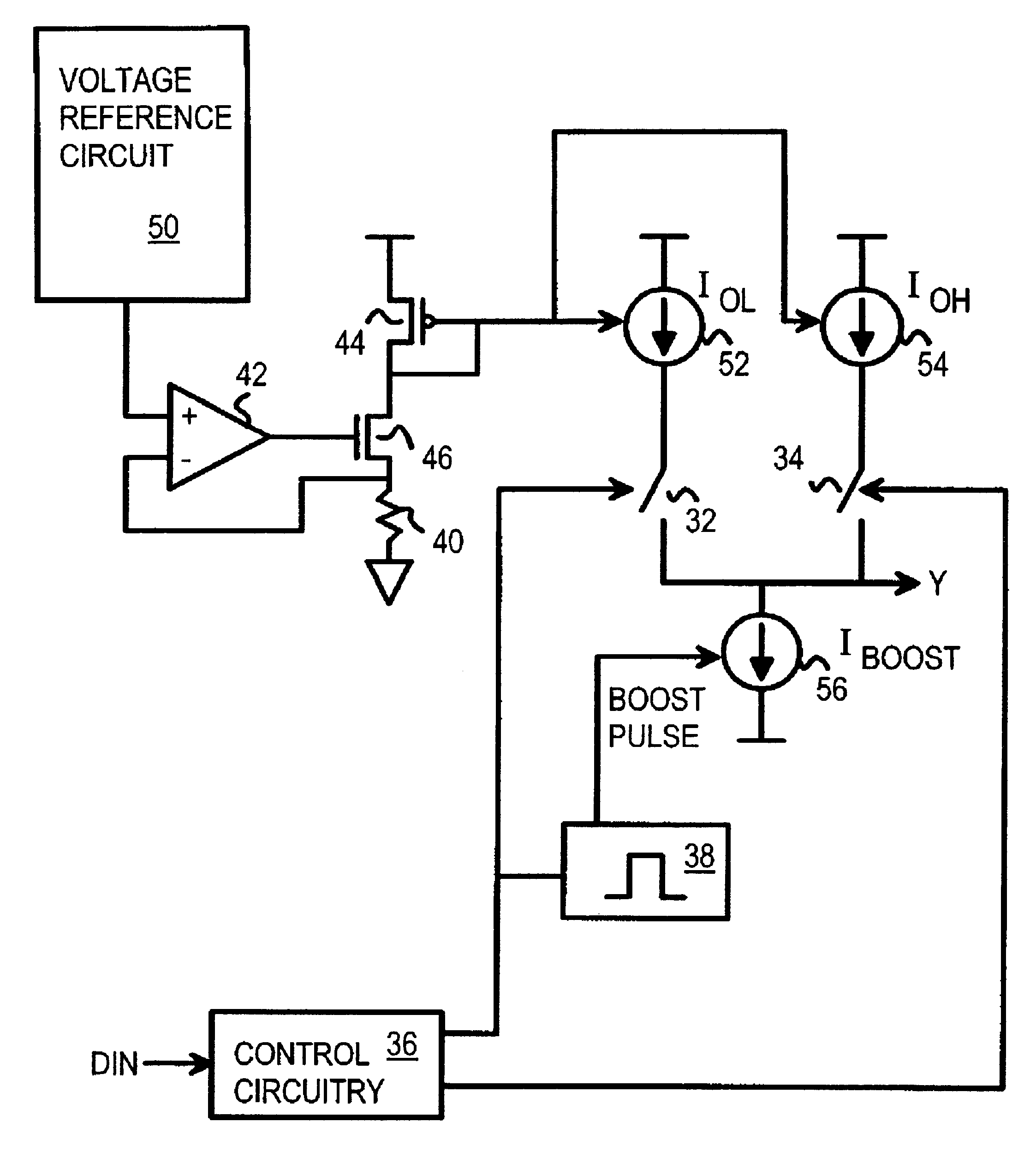
Several other embodiments are contemplated by the inventor. For example. A second current boost could be added in parallel to the IOH current source 54 (FIG. 3) to provide for a boosted pull-up current. This second boosted current source would be activated by a pulse generator that is triggered by the control signal to switch 34. Other VOL and VOH values could be substituted, and different terminating resistance and terminating voltage can be used. Different bias voltages could be applied to the current source transistors to provide different IOH and IOL currents even if the transistors had the same W / L ratio.

Connecting transistor 66 can be removed when coupling noise is not a concern to reduce area for the pull-down circuitry. Different biasing schemes can be used for generation of IOH, IOL: an off-chip resistor can be used (104) instead of an integrated one to have more programmability and better precision for IOH and IOL. An alternative timing can be used to control the current s...


PUM


Abstract

A differential amplifier has a boosted sink current that is turned on by a pulse generator when the output is driven low. This boosted sink current quickly lowers the output to the voltage-output-low VOL level. After the pulse ends, the sink current ends and power is reduced to a lower standby level. A differential pair of switches receives the true and complement data. One switch is closed when the data is true, connecting a current source that sets the standby voltage-output-high VOH level. The other switch is closed when the complement data is high, connecting another current source that sets the standby VOL level. A second differential amplifier with reversed true and complement data drives a complement output for a differential signaling transmitter, such as for a pseudo-emitter-coupled logic (PECL) driver.

Description

BACKGROUND OF INVENTIONThis invention relates to differential signaling drivers, and more particularly pseudo-emitter-coupled logic (PECL) drivers.Low-power circuits have employed full-voltage-swing signaling. For example, a complementary metal-oxide-semiconductor (CMOS) output can swing from ground to the power-supply voltage, such as 0-5 or 0-3 volts. However, as signal speeds increase, unwanted electromagnetic interference (EMI) is increasingly generated, and signal quality deteriorates due to reflections, ringing, and voltage undershoot.Reducing the voltage swing reduces these undesirable effects. However, noise margin is also reduced as the voltage swing is cut. Noise margin can be improved by using two signal wires to transmit a logical signal, rather than just one wire. Such differential signaling has been used for many years in bipolar emitter-coupled logic (ECL) systems.More recently, the benefits of differential ECL signaling and low-power CMOS have been combined in what i...

Claims


Application Information

Patent Timeline
Patent Type & Authority Patents(United States)
IPC IPC(8): H03K19/0185H03K19/173H03K19/00
CPCH03K19/0016H03K19/018528H03K19/1738
Inventor KWONG, DAVID
Owner DIODES INC
Why Eureka
Try Eureka