
Combination of bidirectional- and unidirectional-printing using plural ink types

a technology of ink types and ink types, applied in the field of printing images, can solve the problems of complex control, inability to meet the needs of all inks, and misalignment of dots in the main scanning direction,

Inactive Publication Date: 2003-03-11
SEIKO EPSON CORP
View PDF10 Cites 24 Cited by
  • Summary
  • Abstract
  • Description
  • Claims
  • Application Information

AI Technical Summary

Problems solved by technology

This tends to cause dot misalignment in the main scanning direction.
However, since the required control is complicated in such a case, the correction is usually performed for the printing head as a whole.
If the dot misalignment correction is made commonly to all inks available in a printer as described above, the correction is not always satisfactory to all inks.
This may cause single-color characters and drawings to have jaggy contours consequently.

Method used


Image

  • Combination of bidirectional- and unidirectional-printing using plural ink types
  • Combination of bidirectional- and unidirectional-printing using plural ink types
  • Combination of bidirectional- and unidirectional-printing using plural ink types

Examples


first embodiment

A.

A-1. General Configuration of apparatus:

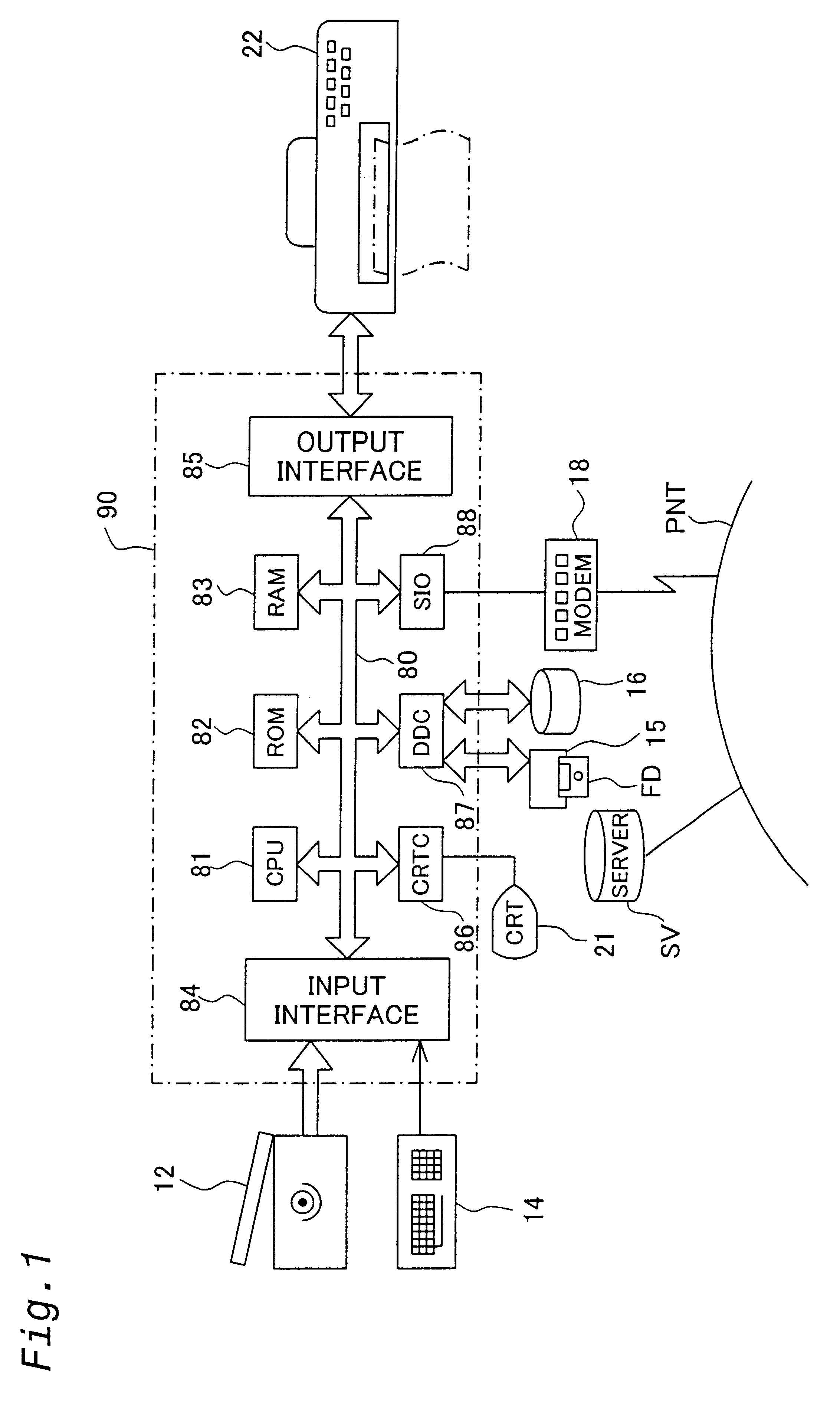
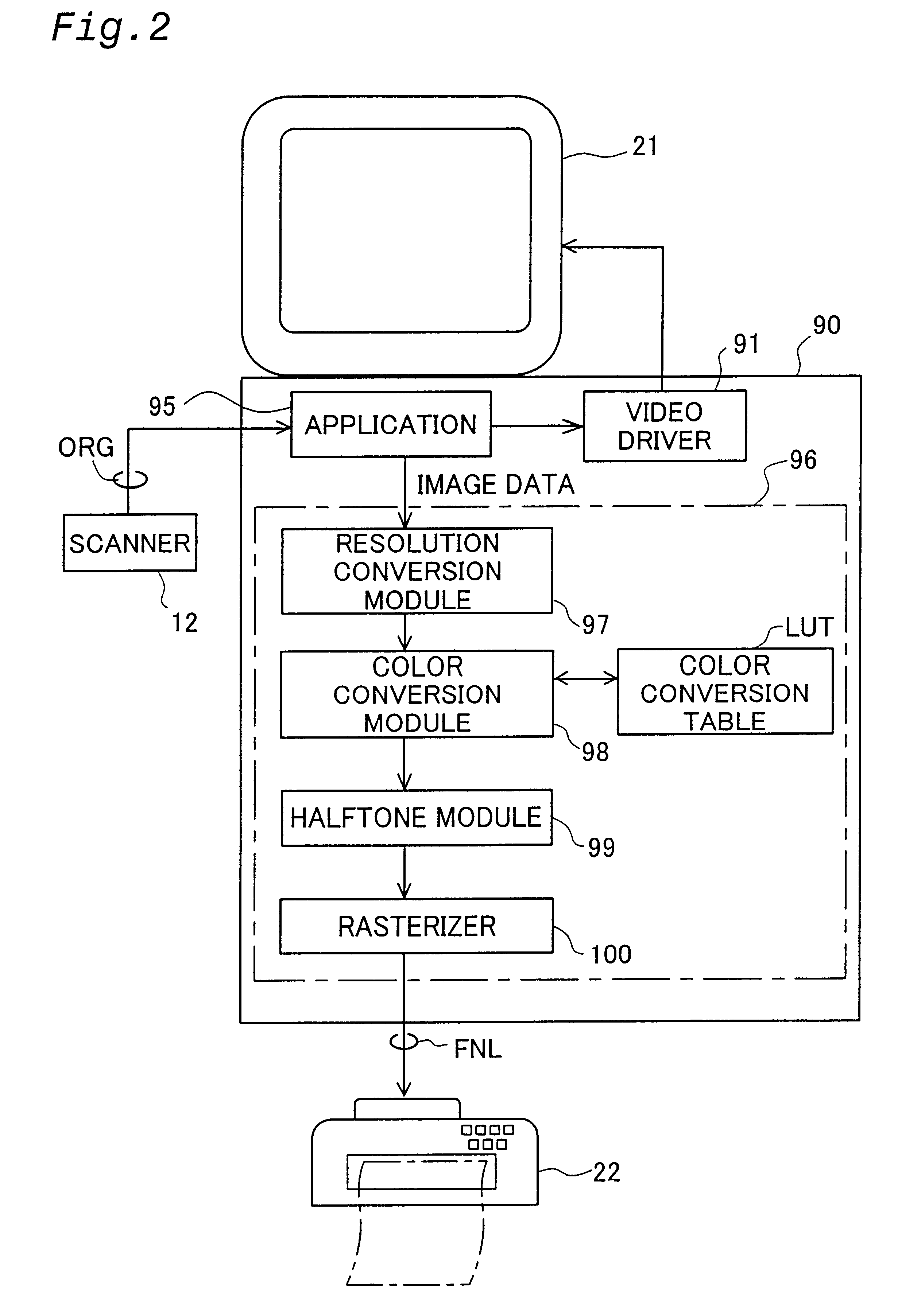
FIG. 1 shows the general configuration of an image processing device and a printer as an embodiment of the present invention. A scanner 12 and a printer 22 are connected to a computer 90. This computer 90 functions as an image processing device as a result of a specified program being loaded and executed. This computer also functions as a printing device together with the printer 22. This computer 90 includes a CPU 81 which performs various types of operational processing in order to control operations for image processing; the computer 90 is also equipped with the respective parts described below, which are connected by a bus 80. The ROM 82 stores in advance various types of programs and data required in order to perform various types of operational processing in the CPU 81. The RAM 83 is a memory for temporarily storing various types of programs and data required in order for the CPU 81 to perform various types of operational processing. T...

second embodiment

B. Second Embodiment

B-1. Configuration of apparatus:

FIG. 9 is a plan view which illustrates the disposition of the nozzles on the printing head 28a of the second embodiment. The printer of the second embodiment differs from the first embodiment in the disposition of the nozzles on the printing head 28a. In all other respects, this embodiment is similar to the first embodiment.

As is shown in FIG. 9, two nozzle rows that extend in the sub-scanning direction SS are installed at a uniform pitch of 2 k on each of the actuators 61a through 63a. The constructions of the second actuator 62a and third actuator 63a are the same as those of the second actuator 62 and third actuator 63 in the first embodiment. However, the construction of the first actuator 61 a differs from that of the first actuator 61 in the first embodiment, in that 20 nozzles are installed in each of the nozzle rows K.sub.1 and K.sub.2. Furthermore, as in the first embodiment, the nozzle row K.sub.1 is installed in positio...


PUM


Abstract

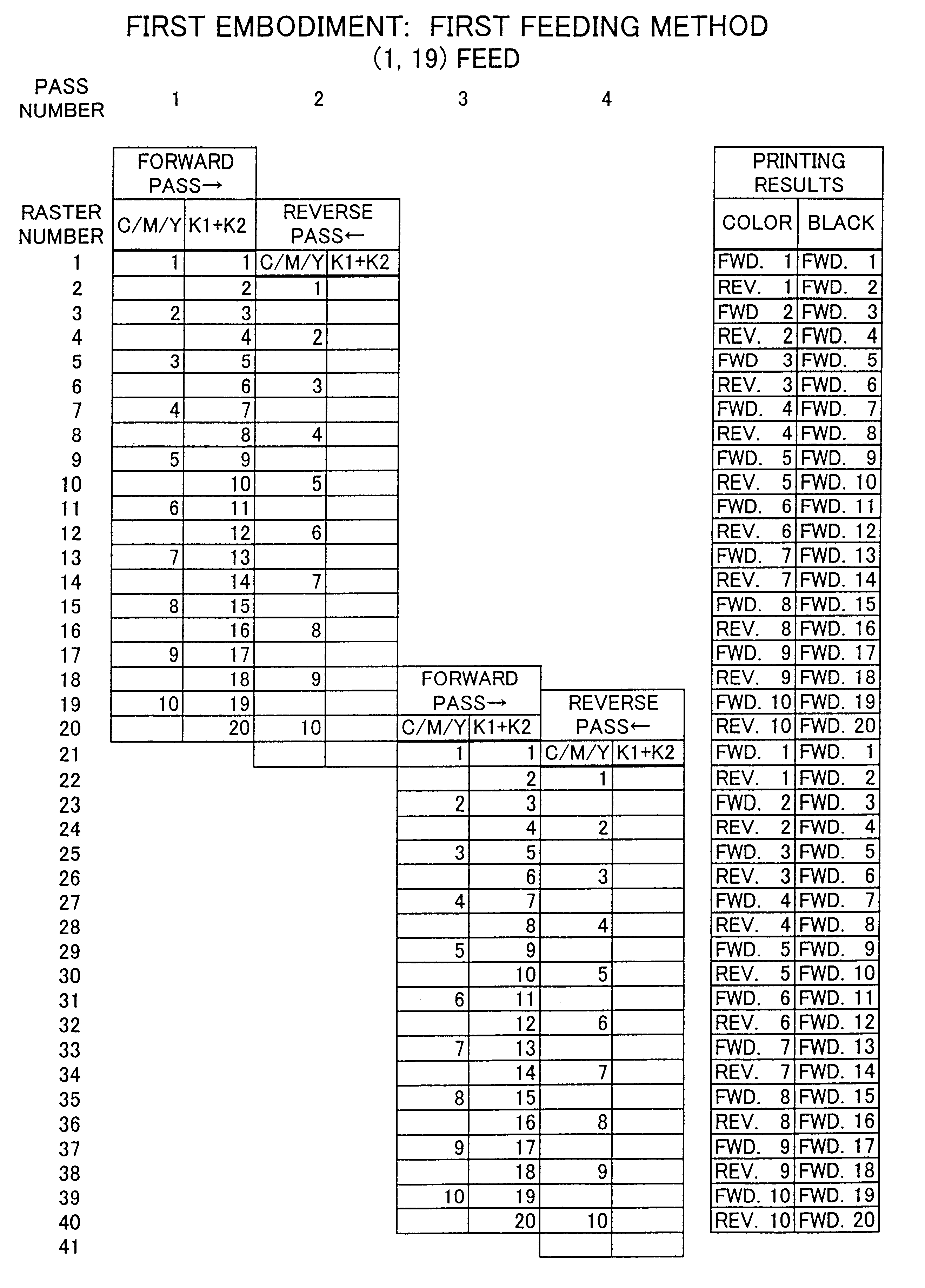
A printing head includes a first type nozzle groups for ejecting respective inks of a first ink group, and a second type nozzle group for ejecting respective inks of a second ink group. The second type nozzle group includes twice the number of nozzles in the first type nozzle group. On the forward passes of the main scanning, ink droplets are ejected from both the first type nozzle group and the second type nozzle group. On the reverse passes of the main scanning, ink droplets are ejected from only from the first type nozzle group. With respect to the first type nozzle group, the ejection timing of the ink droplets is corrected on the reverse passes of the main scanning on the basis of a specific correction value for dot misalignment.

Description

1. Field of the InventionThe present invention relates to a technique for printing images on a printing medium while performing bidirectional main scanning.2. Description of the Related ArtIn recent years, color inkjet printers have spread widely as computer output devices. Inkjet printers typically have a print head including plural nozzles for ejecting ink droplets to form dots on a print medium. Some inkjet printers have a function of so-called "bidirectional printing" in order to increase the printing speed.In the case of bidirectional printing, a print head ejects ink droplets along both the forward and reverse passes of main scanning; as a result, the travel direction of the ink droplets is reversed on the forward and reverse passes. This tends to cause dot misalignment in the main scanning direction. Japanese Laid-Open Gazette No. 5-69625 discloses a technique for solving this dot misalignment problem. In this conventional technique, the amount of the dot misalignment is regi...

Claims


Application Information

Patent Timeline
Patent Type & Authority Patents(United States)
IPC IPC(8): B41J19/14B41J19/00B41J2/21B41J2/01
CPCB41J19/145B41J19/142
Inventor OTSUKI, KOICHI
Owner SEIKO EPSON CORP
Learn More