Compensating for polarisation mode dispersion in optical transmission fibers

a technology of optical transmission fiber and polarisation mode, which is applied in the direction of multiplex communication, cladded optical fibre, instruments, etc., can solve the problems of unsuitable long-haul fibre link electrical approaches and rise to imperfections in the geometric circularity of the fibre, and achieve enhanced birefringence control

Inactive Publication Date: 2004-03-16
RPX CLEARINGHOUSE
View PDF35 Cites 24 Cited by
  • Summary
  • Abstract
  • Description
  • Claims
  • Application Information

AI Technical Summary

Benefits of technology

Control of birefringence can be enhanced by providing additional means, such as stress rods, to alter the

Problems solved by technology

However, manufacturing tolerances, conditions of use, environmental factors and so on, give rise to imperfections in the

Method used


Image

  • Compensating for polarisation mode dispersion in optical transmission fibers
  • Compensating for polarisation mode dispersion in optical transmission fibers
  • Compensating for polarisation mode dispersion in optical transmission fibers

Examples


Embodiment Construction

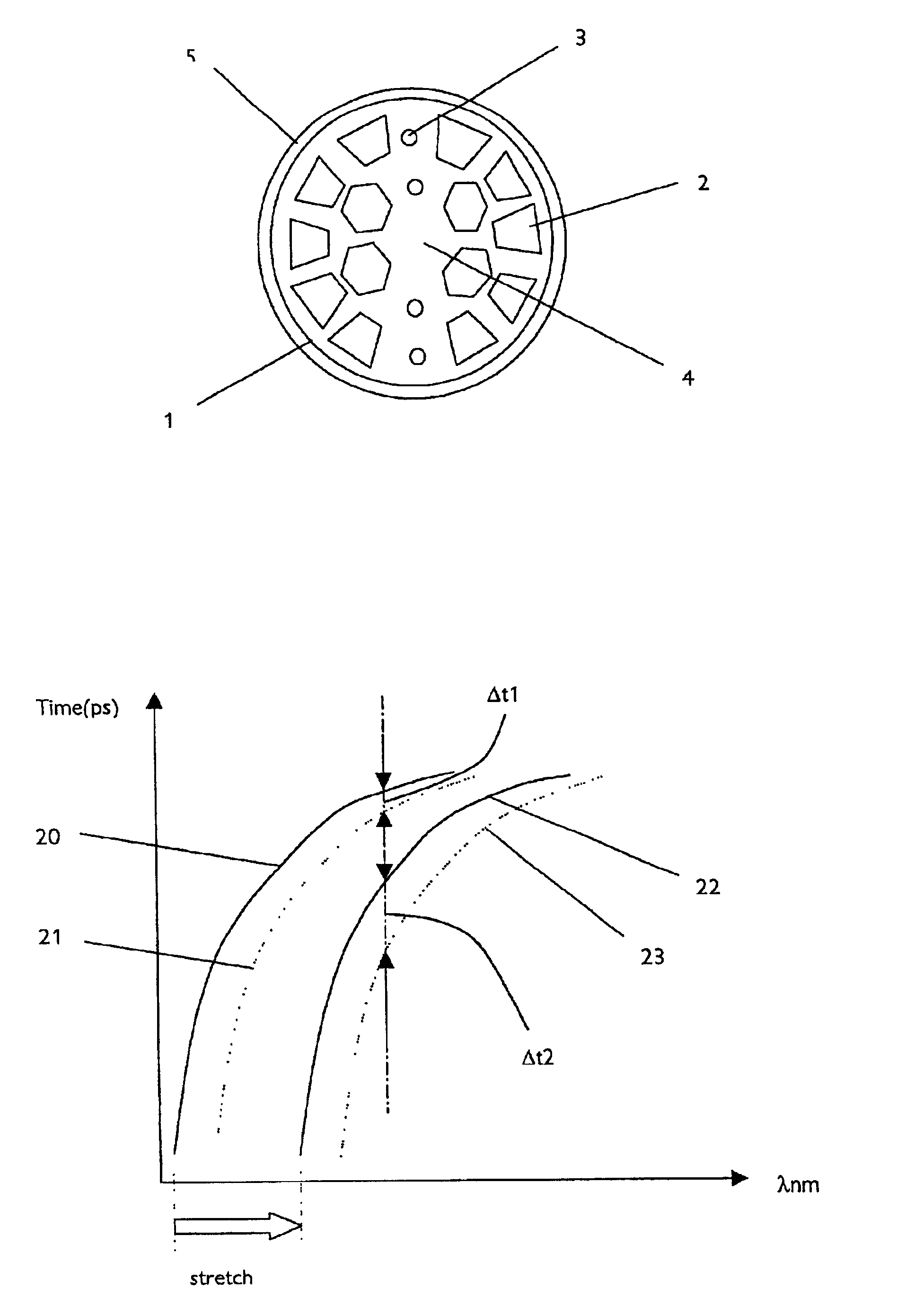
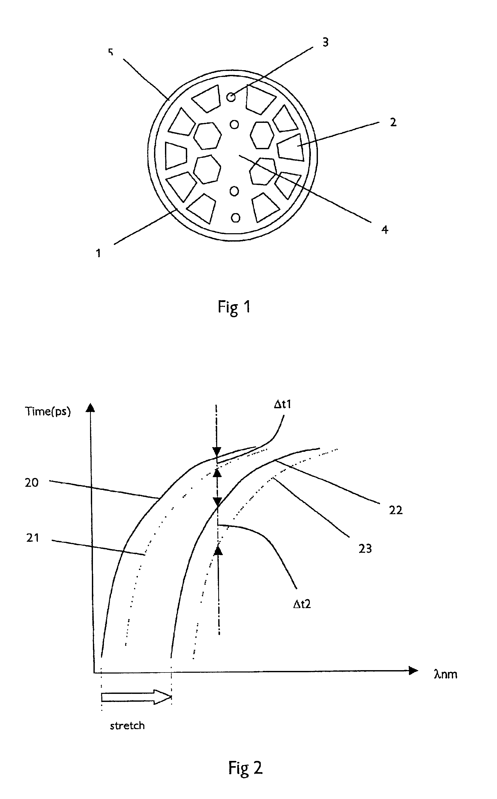
As already mentioned, polarisation mode dispersion arises from the different group velocities attained by orthogonal polarisation states arising from non-perfect circularity of the fibre cross-section and hence birefringence of the fibre. The present invention takes advantage of the effects of birefringence to compensate for the polarisation mode dispersion. It is therefore an advantage to the invention, but not a necessity, to use a fibre having an inherently high birefringence at the outset.

It is known that PCF and HF fibres are highly elliptical in cross section as a result of asymmetries introduced in the manufacturing process. This gives the fibres a higher inherent birefringence than in alternative so-called high birefringence fibres. PCF / HF fibres are made using a variety of techniques, primarily by systematically reducing a pre-form in size to form the geometrically micro-structured optical fibre. For example, the pre-form can be created by micro-drilling an optical pre-form...


PUM


Abstract

Compensating for polarization mode dispersion in a birefringent optical transmission fibre is achieved by controlling the birefringence of the fibre. The difference in group velocity of the orthogonal polarization states of an optical signal transmitted over the fibre is monitored to generate an error signal representing the difference. The birefringence of the fibre is adjusted accordingly to minimize the difference and thereby provide dynamic compensation. Birefringence control may be achieved by a non-linear fibre grating written into the fibre to impose a differential time delay. The fibre may be a side hole fibre (SHF), a holey fibre (HF), a photonic crystal fibre (PCF), or any other suitable microstructure fibre. The fibre may have stressing rods, may be tapered along its length and may be controlled electrically, mechanically, acoustically or thermally by spaced heating elements.

Description

FIELD OF THE INVENTIONThe invention relates to a technique for compensating for polarisation mode dispersion in optical transmission fibres. The invention also includes an optical transmission fibre incorporating means to compensate for polarisation mode dispersion. The invention further relates to an optical signal when subjected to such a fibre and to an equaliser for effecting such compensation.BACKGROUND TO THE INVENTIONOptical transmission fibres for use in optical transmission systems typically comprise a protective jacket surrounding a lower index cladding material enclosing a higher index optical transmission medium capable of supporting optical transmission along its length with little or no signal loss. Light is confined in the core region within such conventional step index fibres by total internal reflection as a result of the step difference in refractive index between the core and the cladding. The fibre and its cladding are near perfect circles in cross-section.Howeve...

Claims


Application Information

Patent Timeline
IPC IPC(8): G02B6/02G02B6/10H04B10/18G02B6/34
CPCG02B6/02109G02B6/02338G02B6/02357G02B6/02371G02B6/02376G02B6/105G02B6/274G02B6/278H04B10/2572G02B6/021
Inventor REYNOLDS, ANDREW LKANELLOPOULOS, SOTIRIS EHANDEREK, VINCENT
Owner RPX CLEARINGHOUSE
Why Eureka
Try Eureka