Carbon fibrous matter, production device of carbon fibrous matter, production method of carbon fibrous matter and deposit prevention device for carbon fibrous matter

a technology of carbon fibrous matter and production device, which is applied in the direction of carbonsing rags, combustion types, lighting and heating apparatuses, etc., can solve the problems of inconvenient industrial operation, fibrous products, and inferior physical properties of carbon

Inactive Publication Date: 2005-04-12
NIKKISO COMPANY
View PDF6 Cites 39 Cited by
  • Summary
  • Abstract
  • Description
  • Claims
  • Application Information

AI Technical Summary

Problems solved by technology

However, this apparatus as the prior art has the following problem.
This problem is such that, when the carbon fibers are produced in a vapor phase with a molten metal as nuclei formed in the furnace of tubular reactor, fibrous products are deposited on the inside surface of the furnace of tubular reactor.
The blocking of the reactor forces an operator to interrupt the production of the carbon fibers and clean the inside of the reactor, which is very inconvenient to industrial operation.
Furthermore, a pyrolytic carbon layer is formed in the fibrous products deposited on the inside surface of the reactor and the carbon fibers deposited on the fibrous products, and causes the physical properties of the carbon to be inferior as the diameter of the fibers gets greater.
The above-mentioned problem is more easily caused in a horizontal furnace of tubular reactor, in which many individual flows by convection are more easily produced at the different sites of the reactor, than in the vertical furnace of tubular reactor.
However, the production of the fibrous products on the inside surface of the reactor can be prevented to some extent, but cannot completely be prevented.
The system using the heat-resisting ceramic balls caused not only the turbulence of the streamline gas flowing through the reactor, but also the degradation of the properties of the va

Method used


Image

  • Carbon fibrous matter, production device of carbon fibrous matter, production method of carbon fibrous matter and deposit prevention device for carbon fibrous matter
  • Carbon fibrous matter, production device of carbon fibrous matter, production method of carbon fibrous matter and deposit prevention device for carbon fibrous matter
  • Carbon fibrous matter, production device of carbon fibrous matter, production method of carbon fibrous matter and deposit prevention device for carbon fibrous matter

Examples


example 1

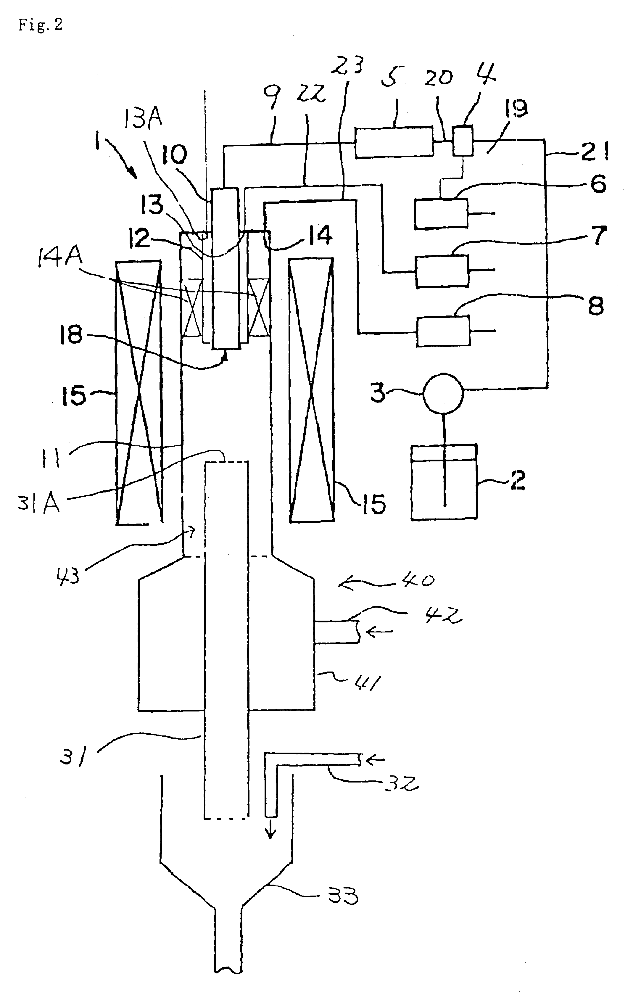
Carbon nanofibers were produced with the apparatus for production of carbon fibrous materials, as shown in FIG. 2, under the following conditions.

(1) Vertical Furnace of tubular reactor 11: Pipe made of silicon carbide

Inner diameter; 9 cm; outer diameter: 10 cm; length: 200 cm;

Distance from the feedstock-supplying nozzle to the bottom opening: 100 cm;

Temperature distribution within the reactor:: Temperature of the uniform-temperature zone (uniformly heated zone) from the feedstock-supplying nozzle down to the position distant by 80 cm from the nozzle: 1120-1100° C.; and temperature of the temperature-reduced zone further down to the position distant by 20 cm from the uniformly heated zone: 1100-900° C.;

Composition of feedstock gas: 0.12 mol % of ferrocene, 0.10 mol % of thiophene, 5.80 mol % of toluene, 93.98 mol % of hydrogen;

Flow rate of the gas supplied from the feedstock-supplying nozzle: 2.60 liters / min.;

Flow rate of the carrier gas (hydrogen) supplied from the cooling gas-supp...

example 2

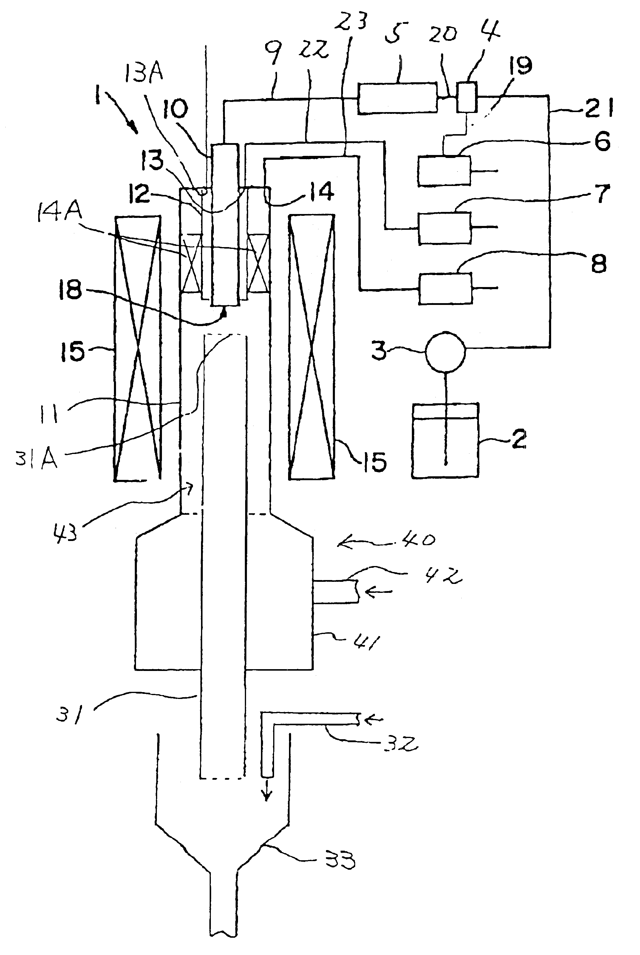
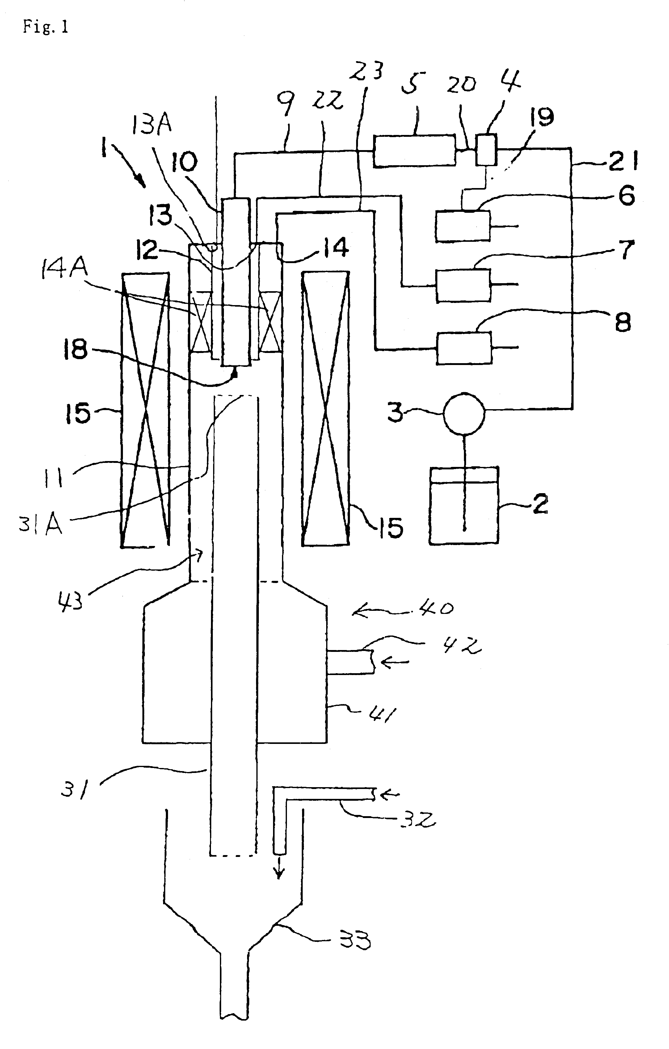
Carbon nanofibers were produced with the apparatus for production of vapor phase deposition carbon fibrous materials, as shown in FIG. 1, and under the following conditions.

(1) Vertical Furnace of tubular reactor 11: Pipe made of silicon carbide

Inner diameter: 9 cm; outer diameter: 10 cm; length: 200 cm.

Temperature distribution within the reactor:: Temperature in the zone between the top end and the position distant by 60 cm from the top end: a temperature gradient from 250° C. to 1120° C.; temperature in the zone between the positions distant by 60 cm and 160 cm, respectively, from the top end: nearly uniform at 1120° C. and temperature in the zone between the position distant by 160 cm from the top end and the bottom end: a temperature gradient from 600° C. to 1120° C.

(2) Feedstock-Supplying Nozzle 10

Nozzle 10 was made of a stainless steel of SUS304, and had an inner diameter of 14 mm and a length of 100 cm, and was surrounded by cooling jacket 12 made of SUS304, which was amounte...

example 3

The same apparatus as mentioned in Example 2 was used to obtain carbon nanofibers, except that some conditions were changed as follows:

(1) Vertical furnace of tubular reactor 11

Temperature distribution within the reactor:: Temperature in the zone between the top end and the position distant by 60 cm from the top end: a temperature gradient from 270° C. to 1180° C.; temperature in the zone between the positions distant by 60 cm and 160 cm, respectively, from the top end: nearly uniform at 1180° C.; temperature in the zone between the position distant by 160 cm from the top end and the bottom end: a temperature gradient of 1180-650° C.

(2) Discharge Pipe 31

Distance from the end of feedstock-supplying nozzle 10 to the top end of discharge pipe 31: 10 cm;

Distance from the top end of furnace of tubular reactor 11 to the top end of discharge pipe 31: 70 cm (Supposing the feedstock gas reached the top end of discharge pipe 10 at the unchanged speed, the retention time of the gas would be 0....


PUM


Abstract

Disclosed is an apparatus for production of vapor-phase growth carbon fibers. The apparatus can continuously produce these carbon fibers for a long time without blocking a furnace of tubular reactor of the apparatus. Also disclosed is a process for production of carbon fibers by means of the apparatus, a device for preventing deposition of carbon fibers on an inside of a furnace of tubular reactor, and vapor-phase growth carbon fibers produced in the apparatus.
The vapor-phase growth carbon fibers include carbon nanofibers and/or carbon nanotubes. The apparatus includes a furnace of tubular reactor, at an end of which a feedstock-supplying nozzle is provided, and a discharge pipe inserted in the furnace of tubular reactor, the top end of which faces the opening of the nozzle and the bottom end discharges the carbon fibers.

Description

BACKGROUND OF THE INVENTION1. Field of the InventionThis invention relates to an apparatus for production of carbon fibrous materials, a process for production of carbon fibrous materials, a device for preventing the deposition of carbon fibrous materials, and the carbon fibrous materials produced by the process, apparatus and device. More particularly, this invention relates to an apparatus for production of carbon fibrous materials, which has a furnace of tubular reactor such as a vertical furnace of tubular reactor having such a structure that the reactor can hardly be blocked in the inside thereof, a process for production of the carbon fibrous materials using the apparatus, a device for preventing the deposition of the carbon fibrous materials on the inside surface of the furnace of tubular reactor such as a vertical furnace of tubular reactor, and the carbon fibrous materials produced by the apparatus, device and process.2. Description of Related ArtAs an apparatus for product...

Claims


Application Information

Patent Timeline
IPC IPC(8): D01F9/127D01F9/133D01F9/12
CPCB82Y30/00D01F9/133D01F9/127
Inventor OHSAKI, TAKASHIKAWAMURA, FUMIO
Owner NIKKISO COMPANY
Why Eureka
Try Eureka