Temperature insensitive VCSEL

a temperature-sensitive, laser technology, applied in semiconductor lasers, laser details, nanotechnology, etc., can solve the problems of inaccuracy monitoring, active cooling, and relatively large power consumption of thermoelectric coolers, and achieve the effect of substantially constant slope efficiency

Inactive Publication Date: 2005-04-12
OPTICAL COMM PRODS
View PDF18 Cites 21 Cited by
  • Summary
  • Abstract
  • Description
  • Claims
  • Application Information

AI Technical Summary

Benefits of technology

The patent describes a type of laser that has multiple quantum wells that work independently over temperature. These quantum wells are also matched in their gain, which ensures that the number of carriers that contribute to stimulated emission remains constant over temperature. This results in a more efficient laser that can operate over a wider range of temperatures.

Problems solved by technology

The technical problem addressed in this patent text is the need for temperature compensation of VCSELs in fiber-optic communication links, as their performance typically varies with temperature. Conventional temperature compensation approaches such as optical feedback and active cooling have their limitations such as inaccurate monitoring and unreliability. In addition, large area photodiodes are required to capture a sufficient percentage of reflected light for accurate feedback. The driver circuitry for optical feedback systems is also complex and increases the cost and power requirements of the system.

Method used


Image

  • Temperature insensitive VCSEL
  • Temperature insensitive VCSEL
  • Temperature insensitive VCSEL

Examples


Embodiment Construction

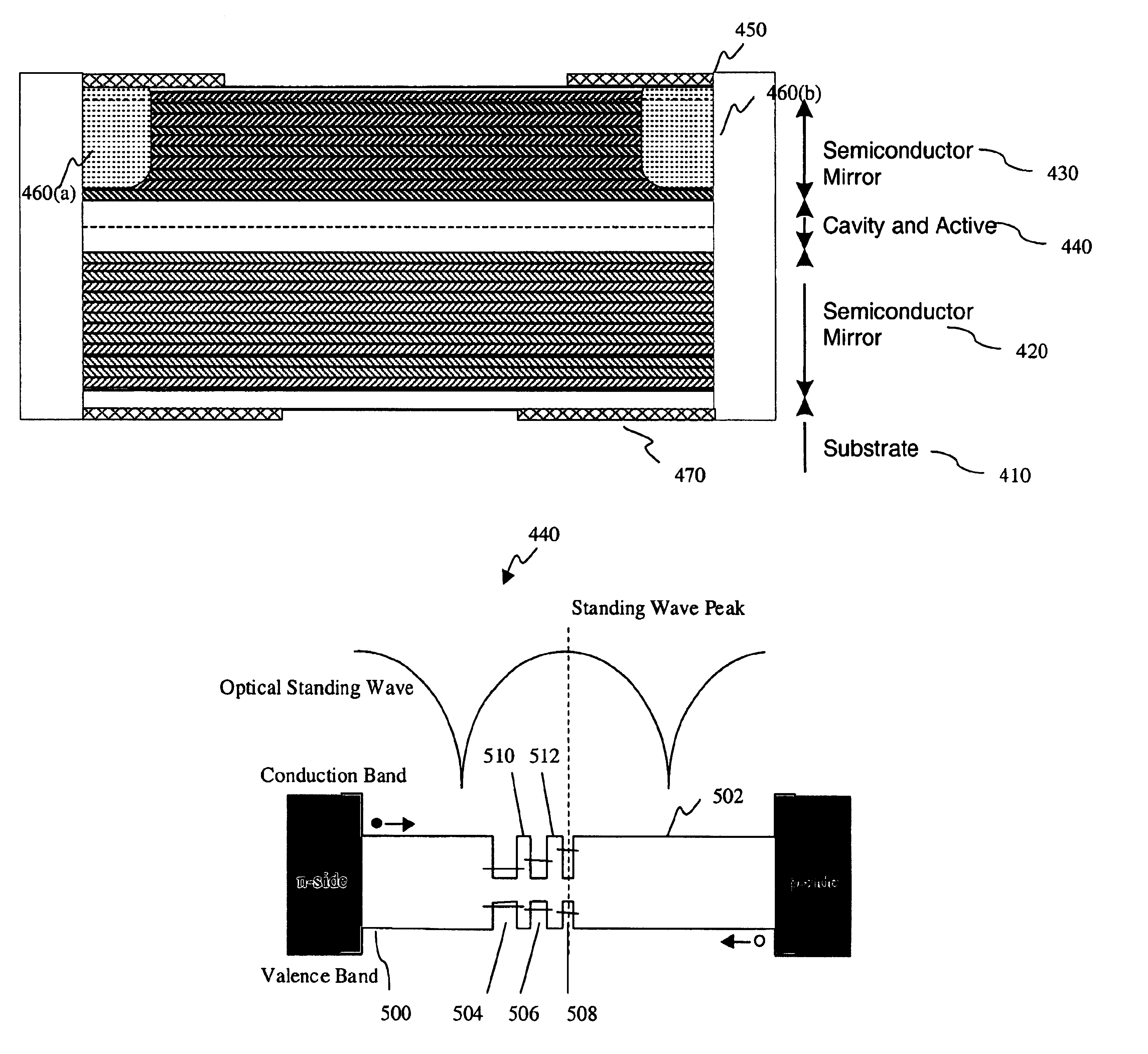
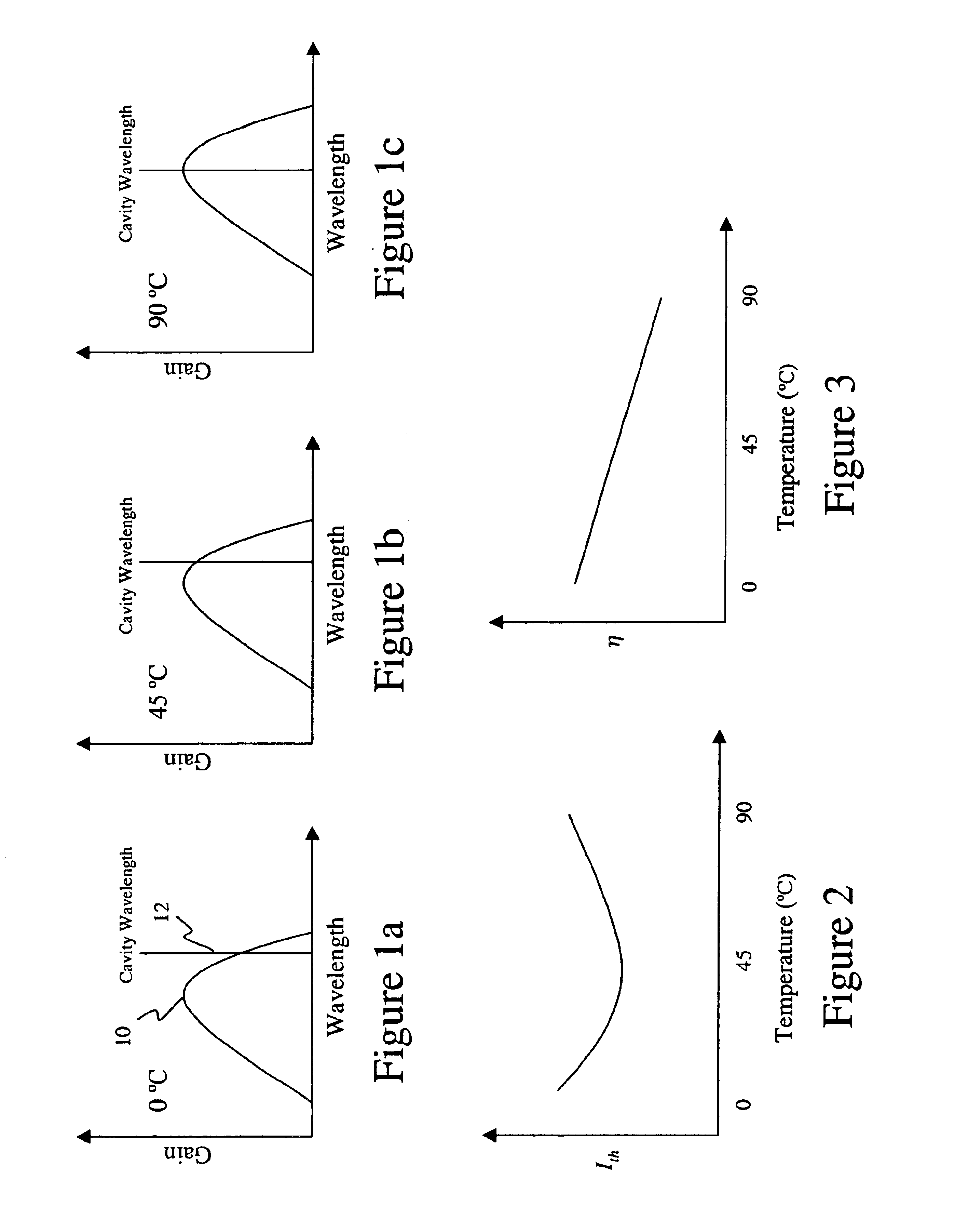
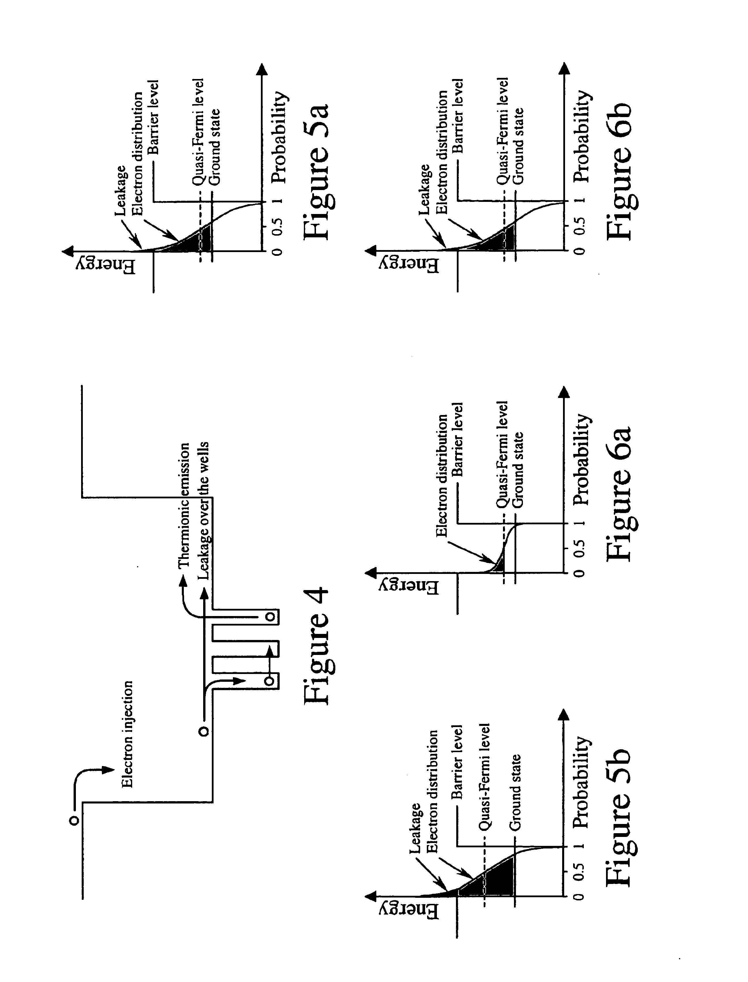
The present invention provides a method and apparatus for stabilizing the performance of surface emitting lasers over a range of operating temperatures. In accordance with an exemplary embodiment the active area of a surface emitting laser may comprise a plurality of quantum wells. In the described exemplary embodiment the gain peak wavelength of the wells or groups of wells may be separated to provide quasi-independent operation over temperature to stabilize the performance of the laser over a range of operating temperatures. In addition, once sufficient gain separation has been achieved, the quantum wells within the active region may be gain matched at different temperatures. In accordance with an exemplary embodiment, a gain matched active region largely maintains the fraction of carriers contributing to stimulated emission, and therefore the internal quantum efficiency, η1, and slope efficiency, η, constant over temperature. In the described exemplary embodiment, gain matching m...


PUM


Abstract

A temperature insensitive vertical cavity laser includes an active region, having a plurality of quantum wells, formed between first and second mirrors. The gain of each of said quantum wells or groups of quantum wells operate quasi-independently at different temperatures such that stimulated emission is dominated by a different quantum well or group of quantum wells at different temperatures.

Description


Claims


Application Information

Patent Timeline
Owner OPTICAL COMM PRODS
Why Eureka
Try Eureka