High efficiency radiant burner

Inactive Publication Date: 2008-09-04
CASCADE DESIGNS INC
View PDF16 Cites 9 Cited by
  • Summary
  • Abstract
  • Description
  • Claims
  • Application Information

AI Technical Summary

Benefits of technology

[0013]In order to increase the efficiency of burner embodiments of the invention, containment vessels, such as pots, can be specially adapted to exploit the quantity and quality of heat output of such burners, as previously intimated. A primary mode of efficiency enhancement comprises the use of integrated or removable heat exchanging structure at or near the bottom of containment vessels. Such structure preferably comprises a plurality of fins, either as fin elements integral with the vessel or as fin bodies attachable to the vessel, arranged to maximize radiant and convective heat transfer of combustion gasses from the burner. Alternatively, efficiency enhancement comprises the use of heat exchanging structure at or near the ou

Problems solved by technology

The result of this arrangement provides for a radiant burner that is has increased resistance to the deleterious effects of wind on the

Method used


Image

  • High efficiency radiant burner
  • High efficiency radiant burner
  • High efficiency radiant burner

Examples


Embodiment Construction

[0024]The following discussion is presented to enable a person skilled in the art to make and use the invention. Various modifications to the preferred embodiments will be readily apparent to those skilled in the art, and the generic principles herein may be applied to other embodiments and applications without departing from the spirit and scope of the present invention as defined by the appended claims. Thus, the present invention is not intended to be limited to the embodiments show, but is to be accorded the widest scope consistent with the principles and features disclosed herein.

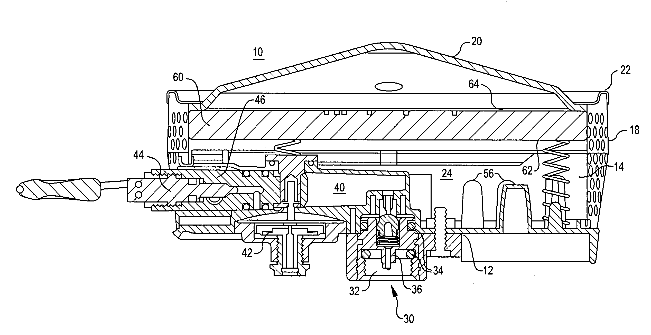
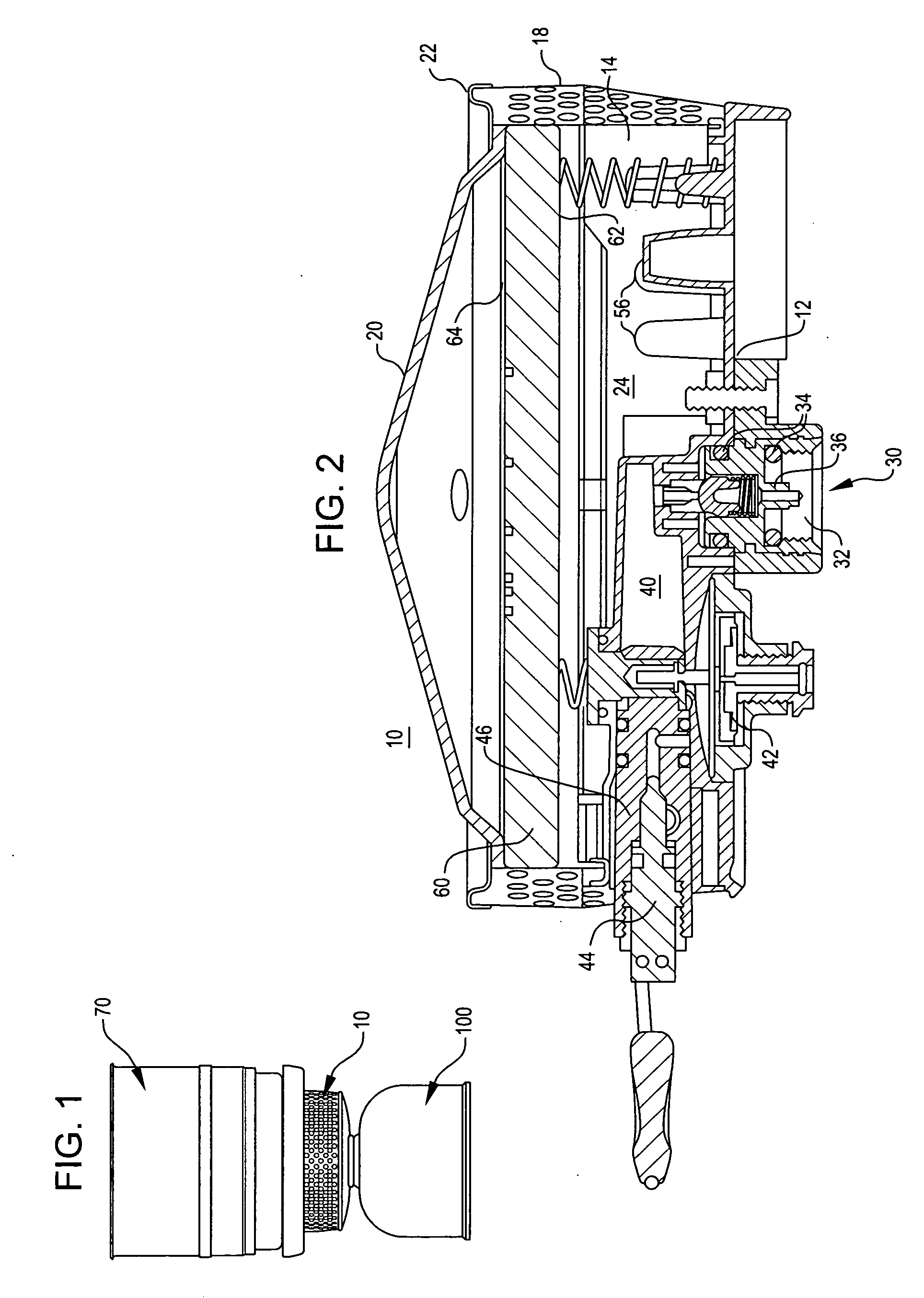
[0025]Unless otherwise noted herein, most parts of burner 10 and heat exchanger 90 are constructed from metal. Depending upon the part's application, the metal may be aluminum, steel, copper, brass or similar conventional metal. The selection of metal is primarily driven by thermal transfer considerations, although resistances to corrosion and high temperatures, as well as weight considerations are als...


PUM


Abstract

A naturally aspirated, fully aerated radiant burner and optional heat exchanger arrangement where the radiant burner has a generally enclosed cavity defined, at least in part, by fuel gas impermeable surroundings and a lower surface of fuel gas permeable burner element, wherein cavity preferably has two opening exposed to an oxidizer source. Sealingly coupled to openings are mix tubes, each having respective first ends and second ends, wherein first ends occupy openings and second ends extend into and are exposed to cavity. Fuel gas injectors, which during use are in fluid communication with fuel gas, are positioned to introduce fuel gas into mix tubes and entrain only slightly more air than needed for stoichiometric combustion. Pre-combustion gasses migrate to upper surface where stable stoichiometric combustion occurs, resulting in low CO and NOx emissions, increased wind resistance and elevated combustion gas temperatures Connecting the heat exchanger directly to the burner further increases its wind resistance and prevents dilution of the combustion gases by wind or free convection.

Description

FIELD OF THE INVENTION[0001]The present invention relates to controlled, low emissions, combustion and more particularly to pressurized hydrocarbon gas burners and most particularly to a liquid pressurized gas (LPG) burner / heat exchanger system that Includes a high efficiency heat exchanger working in conjunction with a fully aerated radiant burner.DESCRIPTION OF THE PRIOR ART[0002]Conventional gas external combustion apparatus traditionally use partially aerated fuel-air mixtures and require introduction of relatively large quantities of secondary air for complete combustion to occur. This dilution of the post combustion gases reduces heat transfer efficiencies into a heat transfer surface, such as a fluid container in a cooking or water heating system, e.g., a pot, or a commercial or residential hot water tank. Additionally, the volume of introduced secondary air is dependent on the apparatus' natural convection and diffusion properties, which limit the driving pressure of the pre...

Claims


Application Information

Patent Timeline
IPC IPC(8): F23D14/28
CPCF23D14/16F23D14/28F23N5/247F23D2203/105F23D2900/14121F23D14/72F23D14/151
Inventor STEPHENS, D. REDWOODPORENSKY, JOHN
Owner CASCADE DESIGNS INC
Why Eureka
Try Eureka