System and method for enhanced thermophotovoltaic generation

a technology of thermophotovoltaic and enhanced generation, applied in thermal-pv hybrid energy generation, pv power plants, instruments, etc., can solve the problems of reducing efficiency, less power being delivered, and cell voltage collapse, so as to reduce fossil fuel nox emissions, increase burner efficiency, and expand the range of useful energy sources

Inactive Publication Date: 2005-05-26
PRACTICAL TECH
View PDF24 Cites 179 Cited by
  • Summary
  • Abstract
  • Description
  • Claims
  • Application Information

AI Technical Summary

Benefits of technology

[0013] Thermal input may be a fossil fuel, solar, geothermal, waste heat, or any combination of these. A catalytic converter or an afterburner may reduce fossil fueled NOx emissions. A recuperator may increase burner efficiency. Highly concentrated insolation from a parabolic dish collector may be used as is. Lower grade solar heat, geothermal, or waste heat may require a heat pump to increase the temperature to a useful level for a TPV emission, expanding the range of useful energy sources. The heat pump also reduces the re-radiation of collected energy from the solar thermal collector tube. Thermal storage may be implemented. The thermal storage may be sized to compensate for diurnal to seasonal solar variations or batch variations in waste heat. The thermal storage and TPV converter may be placed in an environmentally protected area, thus providing Uninterruptible Power Supply functionality. Thermal energy may be provided for heating. Reflective and vacuum insulation reduce thermal losses. System components may be paralleled or bussed in any combination for increased reliability.

Problems solved by technology

Applying an electric load beyond the maximum power point will cause the cell voltage to collapse and even less power will be delivered.
Without the electric energy storage, the system must be backed off of the maximum power point to allow for transient stability, reducing efficiency.

Method used


Image

  • System and method for enhanced thermophotovoltaic generation
  • System and method for enhanced thermophotovoltaic generation
  • System and method for enhanced thermophotovoltaic generation

Examples


Embodiment Construction

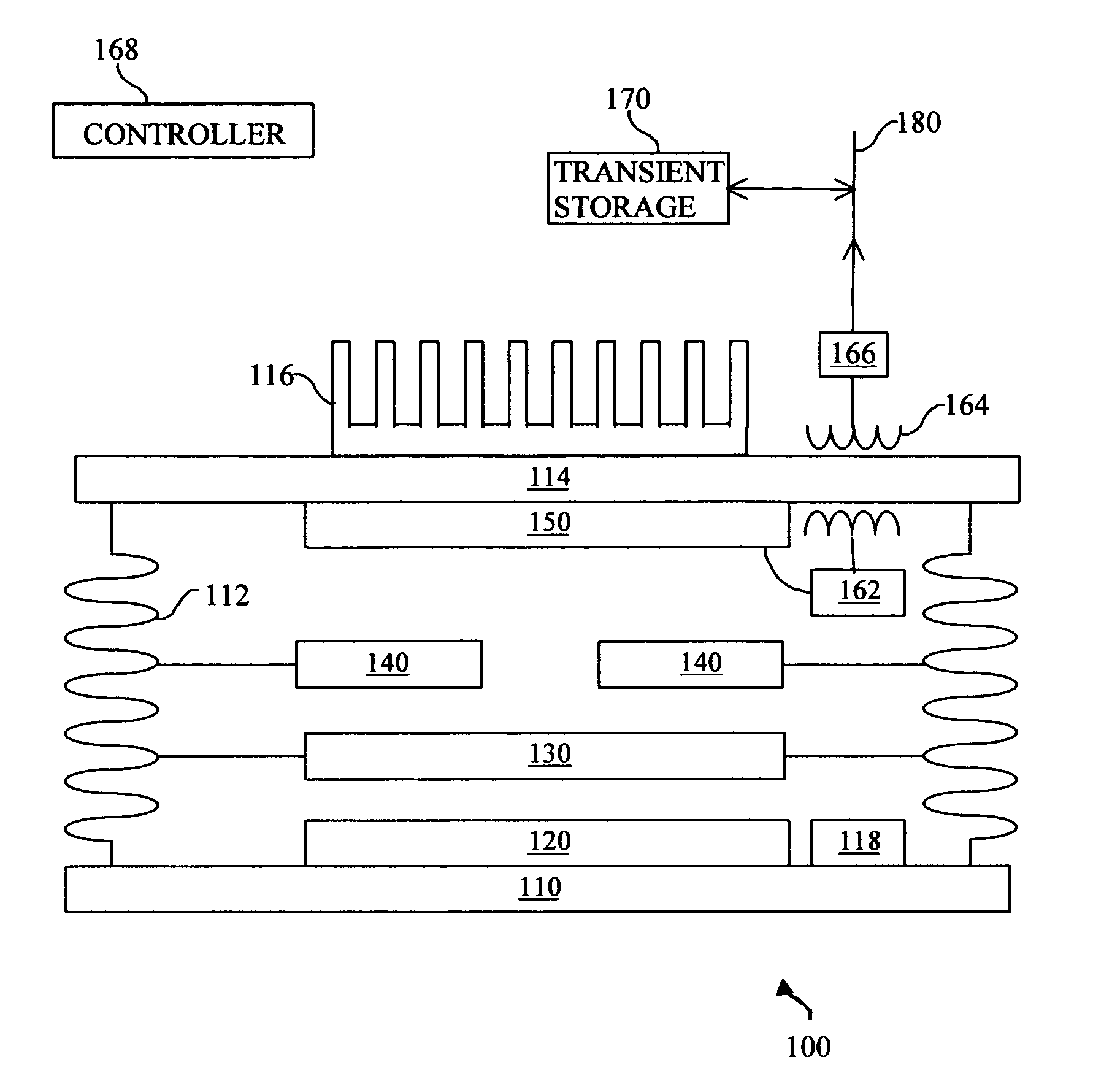
[0021] Embodiments of the present invention and their advantages are best understood by referring to FIGS. 1 through 5 of the drawings, in which like numerals refer to like parts.

[0022]FIG. 1 is a diagram demonstrating one method of TPV power conversion in accordance with the present invention. A variety of thermal energy sources may deliver heat to emitter 120. Emitter 120 is a photonic crystal possessing a PBG. Preferably emitter 120 consists of: two materials with a large refractive index contrast, a full 3 dimensional PBG, a wide PBG, one material has a complex dielectric constant, and has a low manufacturing cost. All or some of these properties may be present in varying degrees. An inverse opal structure offers a low manufacturing cost, beneficial in market acceptance. Other structures such as a woodpile, or a rod and post, may offer higher performance at a higher cost. A 2 dimensional PBG may be used. In other embodiments Emitter 120 may be a rare earth or a micro structured...


PUM


Abstract

A system and method for lower cost, high efficiency, thermophotovoltaic distributed generation includes: an emitter, a photovoltaic cell, and transient electrical energy storage.

Description

RELATED APPLICATIONS [0001] This application claims the priority benefit of U.S. Provisional Application Ser. No. 60 / 518,488, entitiled “System and Method for Thermal to Electric Energy Conversion”, filed Nov. 10, 2003.TECHNICAL FIELD OF THE INVENTION [0002] This invention relates generally to the field of thermophotovoltaic electric generation and more specifically to a high reliability, high efficiency, distributed generation system. BACKGROUND OF THE INVENTION [0003] The field of thermophotovoltaic (TPV) generation suffers for a variety of reasons, including: poor energy conversion efficiency, high installation cost, high generation cost per watt hour, high capital cost, variable load, high peak loads, fuel choice, and low manufacturing volume. These factors severely limit public acceptance. [0004] TPV systems suffer from a poor spectral match between the emitter and the photovoltaic (PV) cells. Emissions with wavelengths below the PV bandgap simply heat the PV and emissions with...

Claims


Application Information

Patent Timeline
Patent Type & Authority Applications(United States)
IPC IPC(8): H01LH01L31/00H01L35/30
CPCB82Y20/00G02B1/005H01L31/02167H02S40/44H01L31/0304Y02E10/60H02S10/30H01L31/028Y02E10/50
Inventor MARSHALL, ROBERT A.
Owner PRACTICAL TECH
Why Eureka
Try Eureka