Gas burner and hob comprising a gas burner

Active Publication Date: 2020-08-13
ELECTROLUX APPLIANCES
View PDF5 Cites 1 Cited by
  • Summary
  • Abstract
  • Description
  • Claims
  • Application Information

AI Technical Summary

Benefits of technology

[0004]It is an objective of the embodiments of the present invention to provide a gas burner with improved gas-primary air mixture capabilities and improved burner efficiency. The objective is solved by

Problems solved by technology

Disadvantageously, the apertures forming the flame ports are quite small and therefore are difficult to clean.
In addition, said ga

Method used


Image

  • Gas burner and hob comprising a gas burner
  • Gas burner and hob comprising a gas burner
  • Gas burner and hob comprising a gas burner

Examples


Embodiment Construction

[0030]The present invention will now be described more fully with reference to the accompanying drawings, in which example embodiments are shown. However, this invention should not be construed as limited to the embodiments set forth herein. Throughout the following description similar reference numerals have been used to denote similar elements, parts, items or features, when applicable.

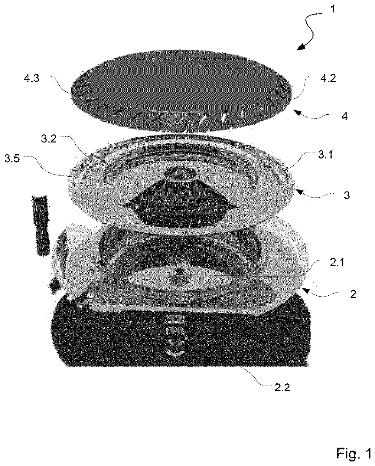
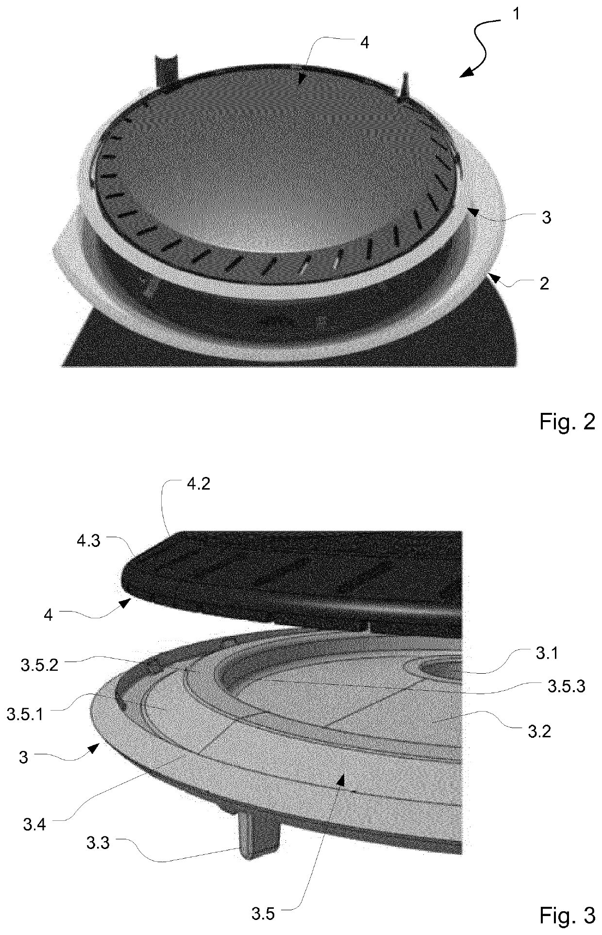
[0031]FIG. 1 illustrates an embodiment of a gas burner 1 in an exploded view and FIG. 2 illustrates said gas burner 1 after assembling. The gas burner 1 comprises an injector holder 2. Said injector holder 2 may comprise a cup-like or essentially cup-like shape. More in detail, the injector holder 2 may comprise a circumferential flange by which the injector holder 2 can be fixed in traditional manner to a cooking hob.

[0032]The injector holder 2 may comprise a base portion at which a seat for a gas injector 2.1 is provided. The gas injector may be arranged such that gas is ejected in a vertical or e...


PUM


Abstract

The invention relates to a gas burner comprising: —an injection holder (2) with a gas injector (2.1);—a burner body (3) adapted to be arranged at the injection holder (2), the burner body (3) comprising an opening (3.1) for enabling a gas flow from said gas injector (2.1) and a primary air flow in an area above said burner body (3); —a burner cap (4) adapted to be arranged at the top side of the burner body (3), the burner cap (4) comprising a bottom portion (4.1) and a circumferential surface portion (4.2) protruding downwardly from said bottom portion (4.1), wherein the circumferential surface portion (4.2) comprises a plurality of flame ports (4.3) and said burner body (3) and said burner cap (4) confine a chamber (5) for providing a combustion mixture of gas and primary air; wherein the burner body (3) comprises a bulge-shaped protrusion (3.5) forming a continuous ridge below the burner cap (4) at least in the area in which the flame ports (4.3) are provided, said bulge-shaped protrusion (3.5) reducing the distance between the burner cap (4) and the burner body (3) in the area of the flame ports (4.3).

Description

[0001]Generally, the present invention relates to the field of gas burners. More specifically, the present invention relates to a gas burner with a burner body and a burner cap comprising flame ports, the burner body and the burner cap confining a distribution chamber for providing a combustion mixture of gas and primary air.BACKGROUND OF THE INVENTION[0002]Gas burners are well-known in prior art. Specifically, cooking hob gas burners are known which comprise an injection holder for coupling the gas burner with the cooking hob, a burner body and a burner cap. Said burner body and burner cap form a combustion gas chamber providing a mixture of gas and primary air to a plurality of flame ports.[0003]Disadvantageously, the apertures forming the flame ports are quite small and therefore are difficult to clean. In addition, said gas burners show a limited capability of managing the speed of gas-primary air mixture which limits the efficiency of the gas burner.SUMMARY OF THE INVENTION[000...

Claims


Application Information

Patent Timeline
IPC IPC(8): F23D14/06F23L1/00
CPCF23L1/00F23D14/06F23D2212/20F23D2203/1026
Inventor RASI, FABIOBEGHI, MAURIZIO
Owner ELECTROLUX APPLIANCES
Why Eureka
Try Eureka