Method and device for writing control and image forming device

a technology of image forming device and writing control method, which is applied in the direction of electrographic process equipment, instruments, printing, etc., can solve the problems of image quality degradation, inability to truly reproduce original image, and inability to avoid the so as to avoid the effect of color deviation of toner imag

Inactive Publication Date: 2005-05-10
RICOH KK
View PDF16 Cites 8 Cited by
  • Summary
  • Abstract
  • Description
  • Claims
  • Application Information

AI Technical Summary

Benefits of technology

[0028]According to the foregoing description, an object of this invention is to provide a writing control method, a writing control device and an image forming device capable of avoiding a color deviation of a toner image, caused by that the main scanning synchronizing signal and the image forming start signal of the sub-scanning direction are not synchronized.
[0029]Another object of this invention is to provide an image forming device capable of suppressing a dot position shift in a sub-scanning direction to improve the image quality.

Problems solved by technology

However, according to this method, when time t1 is right before time T / 2 and time t2 is right after time T / 2, the toner image of the first color and the toner image of the second color cannot be avoided from being shifted close to one line.
Therefore, the image quality is degraded and the original image cannot be truly reproduced.

Method used


Image

  • Method and device for writing control and image forming device
  • Method and device for writing control and image forming device
  • Method and device for writing control and image forming device

Examples


second embodiment

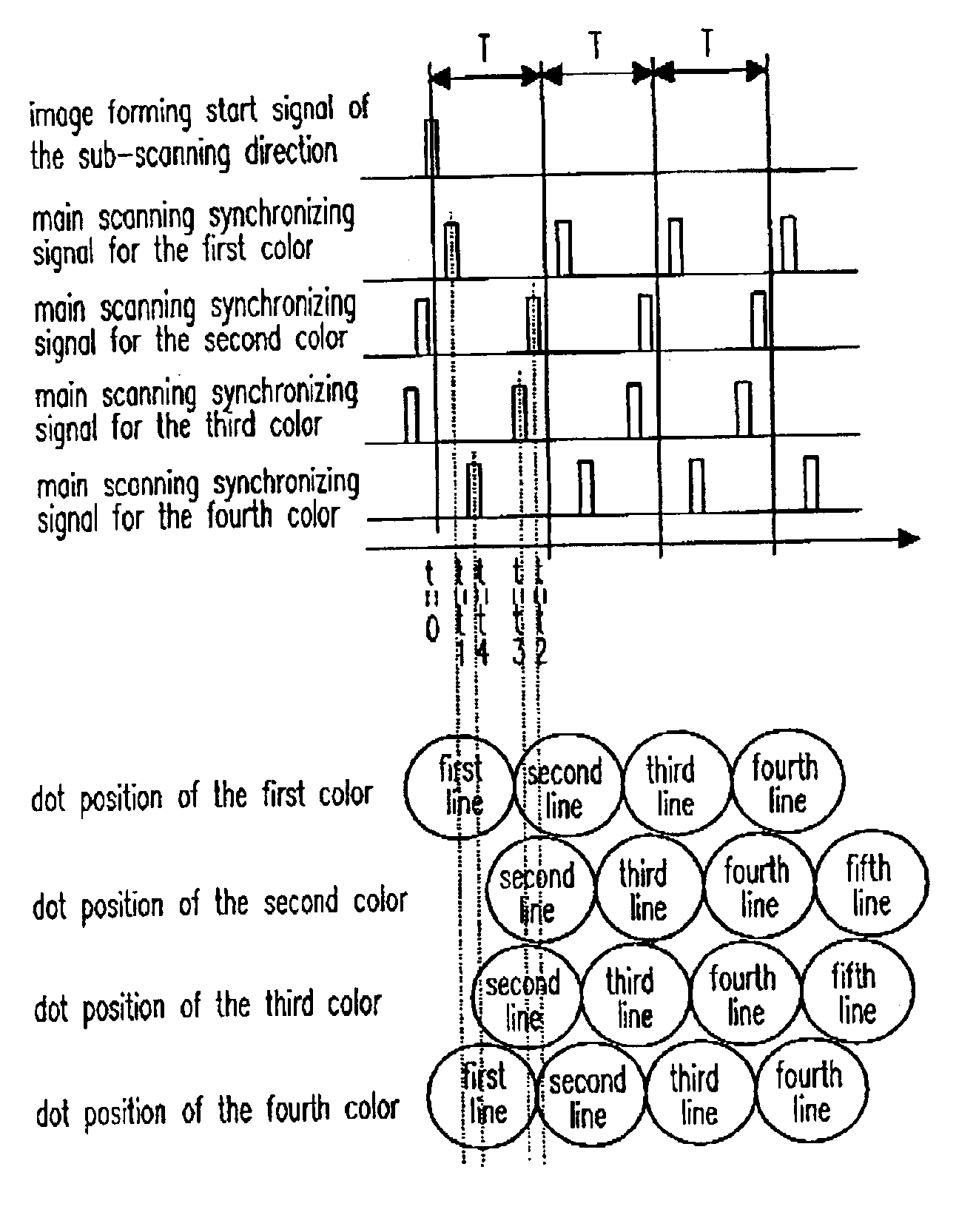
[0109]FIG. 11 shows dot positions formed according to the In the situation shown in FIG. 8, time t1 is equal to or larger than T / 2 in the exposure for the first color, |t1−t2| is equal to or larger than T / 2 in the exposures for the second and the fourth colors, and time |t1−t2| is smaller than T / 2 in the exposure for the third color. Therefore, by implementing Steps 5, 6 and 7 shown in FIG. 10A, the exposure for the first color starts from image information of the second line. In addition, by implementing Steps 9, 10 and 11 shown in FIG. 10B, the exposure for the second and the fourth colors start from image information of the first line. The exposure for the third color starts from image information of the second line. By performing an exposure control in the aforementioned manner, when time t1 is equal to or larger than T / 2, position shifts of image information of the second line and after the second line of the second, the third and the fourth colors can be suppressed to half of...

third embodiment

[0118] a color deviation of the toner image, which is caused by that the main scanning synchronizing signal and image forming start signal of the sub-scanning direction are not synchronized, can be avoided. Furthermore, by using an assumptive image, which averages positions in the sub-scanning direction of the image where the scanning operation has been started by the optical writing device, as a reference image, position shifts of image where scan starts from the third one can be further reduced.

[0119]Next, the fourth embodiment according to the present invention is described in detail. In the image forming device of the fourth embodiment, only an exposure control corresponding to image information of the second, the third and the fourth colors, which is implemented by the exposure control unit 116a, is different from the second embodiment. In the fourth embodiment, the exposure control unit 116a executes substantially the flow chart shown in FIG. 7B, but two steps the same as Step...

fifth embodiment

[0129]FIG. 18 is an example of dot positions formed according to the present invention. FIG. 18 depicts a case of n=4, and a signal with the solid line and its subsequent three signals with dash lines represent dot positions by the optical writing with four beams. In the drawing, dash line portions and solid line portions are separated depicted. However, in fact, what kind of the main scanning synchronizing signal is detected depends on a detecting device for the main scanning synchronizing signal and the exposure control method. Namely, the detection of the main scanning synchronizing signal depends on whether all four beams are emitted. When plural beams are emitted during the detection of the main scanning synchronizing signal, the main scanning synchronizing signal detecting means depends in detecting all emitted beams or only a portion of beams. In the drawing, the main scanning synchronizing signal is input once only is divided into the dash line part and the solid line part f...


PUM


Abstract

An image forming device is provides, which comprises a body to be scanned that moves in a sub-scanning direction; a writing means for scanning the body in a main scanning direction with a light beam according to image information to form a reference image on the body and repeating the scanning plural times to form plural images; and a second body on which the plural images are overlaid to form a color image. The writing means starts writing the reference image at a start time ty1 when a main scanning synchronizing signal is firstly generated by the writing means after a time tx1 when a predetermined time has lapsed from detection of an image forming start signal of the sub-scanning direction for the reference image. A start time for an image other than the reference image is changed depending on the start time of the reference image.

Description

CROSS-REFERENCE TO RELATED APPLICATION[0001]This application claims the priority benefit of Japanese applications serial no. 2002-060145, filed on Mar. 6, 2002 and serial no. 2002-149171, filed on May 23, 2002.BACKGROUND OF THE INVENTION[0002]1. Field of the Invention[0003]This invention relates in general to a writing control method, a writing control device and an image forming device. More particularly, the invention relates to an image forming device using an intermediate transcriber, such as a copy machine, a printer or a facsimile, etc.[0004]2. Description of the Related Art[0005]An image forming device, such as a copy machine, a printer or a facsimile, etc., is well known in the conventional art. The image forming device includes a scanning and writing device that is used to perform a scanning operation in a main scanning direction for image information according to a main scanning synchronizing signal that is detected after an image forming start signal in the sub-scanning d...

Claims


Application Information

Patent Timeline
Patent Type & Authority Patents(United States)
IPC IPC(8): G03G15/01
CPCG03G15/0121G03G15/0194G03G2215/0106G03G2215/0119G03G2215/0161G03G15/0168G03G15/0184
Inventor TAKEYAMA, YOSHINOBUYANAGAWA, NOBUYUKIMATSUURA, NEKKA
Owner RICOH KK
Why Eureka
Try Eureka