A display panel and its manufacturing method

A manufacturing method and display panel technology, which is applied in the field of color display, can solve the problems that the display is difficult to realize and optical flatness, and achieve the effects of avoiding deviation and improving image quality

Active Publication Date: 2019-05-14
江苏锦润光电有限公司
View PDF6 Cites 0 Cited by
  • Summary
  • Abstract
  • Description
  • Claims
  • Application Information

AI Technical Summary

Problems solved by technology

[0007] In order to keep the two interference surfaces absolutely parallel, the two interference surfaces usually maintain a certain flatness, so that the distance between the two is consistent and achieves absolute parallelism. However, it is difficult to achieve optical The sense of flatness, especially for large pixels and low resolution displays is more difficult to achieve

Method used


Image

  • A display panel and its manufacturing method
  • A display panel and its manufacturing method
  • A display panel and its manufacturing method

Examples


Embodiment 2

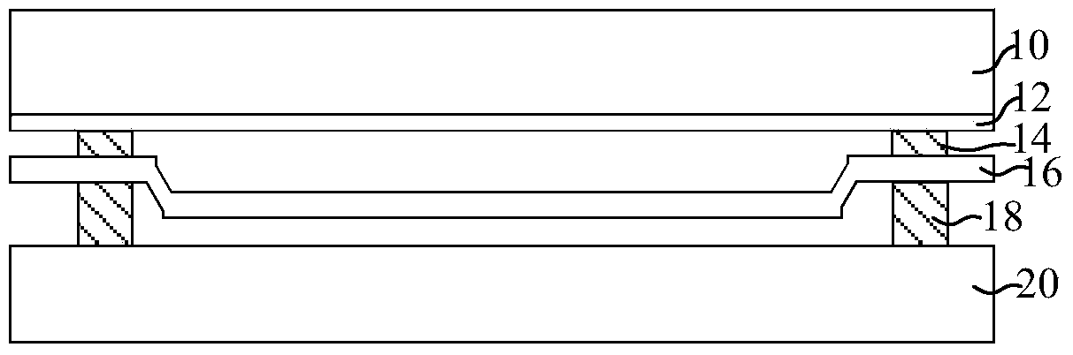
[0079] The manufacturing method of Embodiment 1 has been described in detail above. In Embodiment 2, the same as Embodiment 1, the heat-pressing process is used to laminate the formed light-transmitting substrate and reflective plate, and then, heat-pressing process, so that the surface of the reflective plate facing the semi-transparent reflective layer is parallel to the reflective surface of the light-transmitting substrate. After the pressing process, while flattening the interference surface, the fixation of the reflective plate or the light-transmitting substrate is realized. Parts that are different from those in Embodiment 1 will be described below, and the same parts will not be described again.

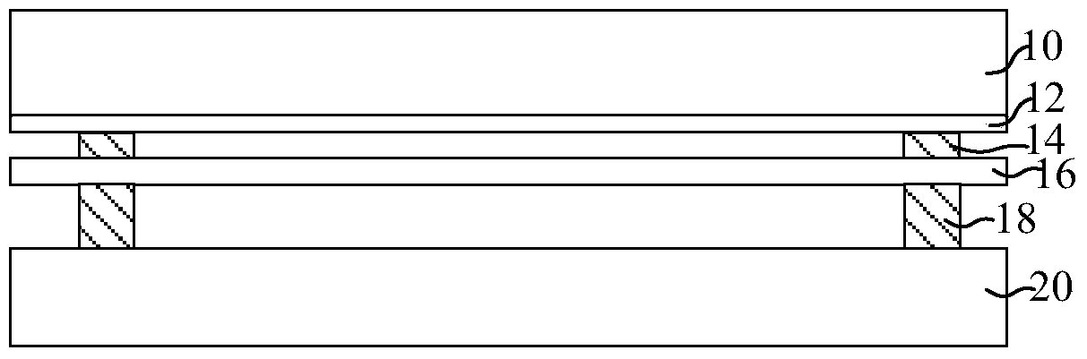
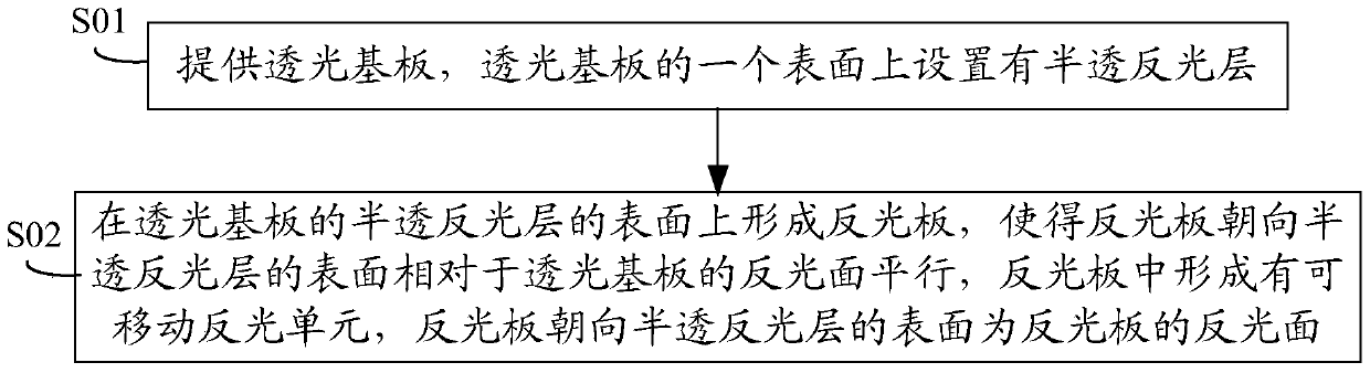
[0080] In step S201, a light-transmitting substrate is provided, and a light-transmitting substrate 100 is provided, and a semi-transparent and reflective layer 110 is provided on one surface of the light-transmitting substrate 100. Refer to Figure 4 shown.

[0081] In st...

Embodiment 3

[0092] The difference from Embodiment 1 and Embodiment 2 is that in this embodiment, after the light-transmitting substrate is provided, a molding plate with light-reflecting units is directly formed on the surface of the translucent reflective layer of the light-transmitting substrate through an injection molding process, and then A reflective film is formed on the surface of the forming plate facing the translucent reflective layer, thereby forming a reflective plate. Parts different from those in Embodiment 1 and Embodiment 2 will be described below, and the same parts will not be repeated.

[0093] In step S301, a light-transmitting substrate is provided, and a light-transmitting substrate 100 is provided, and a semi-transparent and reflective layer 110 is provided on one surface of the light-transmitting substrate 100. Refer to Figure 4shown.

[0094] Same as step S101 in Embodiment 1.

[0095] In step S302, a forming plate 201 with a plurality of reflective units 210 ...

Embodiment 4

[0104] The difference from Embodiment 1 and Embodiment 2 is that in this embodiment, after the light-transmitting substrate is provided, a molding plate with a light-reflecting unit is directly formed on the surface of the translucent reflective layer of the light-transmitting substrate through a photocuring molding process , and then form a reflective film on the surface of the forming plate facing the translucent reflective layer, thereby forming a reflective plate. Parts different from those in Embodiment 1 and Embodiment 2 will be described below, and the same parts will not be described again.

[0105] In step S401, a light-transmitting substrate is provided, and a light-transmitting substrate 100 is provided, and a semi-transparent and reflective layer 110 is provided on one surface of the light-transmitting substrate 100. Refer to Figure 4 shown.

[0106] Same as step S101 in Embodiment 1.

[0107] In step S402, a molding plate 201 with a plurality of reflective unit...


PUM

PropertyMeasurementUnit
thicknessaaaaaaaaaa

Abstract

The invention provides a display panel and a manufacturing method thereof. The method includes the following steps: providing a light-transmitting substrate of which one surface is provided with a semi-light-transmitting reflective layer thereon; the surface of the semi-light-transmitting reflective layer of the light-transmitting substrate forming a reflective plate, such that the surface that faces towards the semi-light-transmitting reflective layer of the reflective plate is parallel to a reflective surface of the light-transmitting substrate, forming a movable reflective unit in the reflective plate, the surface of the reflective plate that faces towards the semi-light-transmitting reflective layer acting as the reflective surface of the reflective plate. The method guarantees that the light-transmitting substrate and the reflective plate are parallel in corresponding parts, realizes substantially flattened interface surfaces, obviates the need for the limit on height differences in distances of the two interface planes by absolute flatness, thus preventing deflection of color display and increasing imaging quality.

Description

technical field [0001] The invention relates to the technical field of color display, in particular to a display panel and a manufacturing method thereof. Background technique [0002] The reflective flat panel display utilizes external natural light to irradiate the display panel to form reflected light without using a backlight source. It consumes less power and can be used directly under strong light, so it has a wide range of application prospects. [0003] The display principles of the current reflective flat panel display technology mainly include: the principle of electrophoresis or electrowetting, the principle of bistable liquid crystal light diffraction and the principle of light interference, etc. The reflective flat panel display based on the principle of light interference uses incident natural light to generate mutual interference of reflected light on different film layers of the display unit to display any color in the continuous spectrum. [0004] Such as ...

Claims


Application Information

Patent Timeline
Patent Type & Authority Patents(China)
IPC IPC(8): G02B26/00G02F1/21G09F9/37
CPCG02B26/001G02F1/21G09F9/37
Inventor 季中张厚明林金梅
Owner 江苏锦润光电有限公司
Why Eureka
Try Eureka