Binding unit for sports devices, in particular for a snowboard

a technology for sports devices and binding units, applied in the direction of ski bindings, skis, sports apparatus, etc., can solve the problems of tearing apart the base plate and retaining disc, and the release and locking mechanism used to adjust the rotation angle can only be operated by applying a considerable amount of force, so as to improve the binding unit

Inactive Publication Date: 2005-06-28
ATOMIC AUSTRIA
View PDF18 Cites 49 Cited by
  • Summary
  • Abstract
  • Description
  • Claims
  • Application Information

AI Technical Summary

Benefits of technology

[0005]The underlying objective of the present invention is to provide a binding unit for sports devices, in particular for a snowboard, which enables the angular position relative to the sports device to be changed rapidly and effortlessly. Irrespective of the above, another objective of the invention is to improve the binding unit by optionally incorporating simple technical means so that the relative position of the binding unit can be changed in the longitudinal direction of the sports device rapidly and with out complications.

Problems solved by technology

One disadvantage of the known binding units resides in the fact that either the base plate and retaining disc can be torn apart by a maximum force that is relatively low or the release and locking mechanism used to adjust the angle of rotation can only be operated by applying a considerable amount of force.

Method used


Image

  • Binding unit for sports devices, in particular for a snowboard
  • Binding unit for sports devices, in particular for a snowboard
  • Binding unit for sports devices, in particular for a snowboard

Examples


Embodiment Construction

[0055]Firstly, it should be pointed out that the same parts described in the different embodiments are denoted by the same reference numbers and the same component names and the disclosures made throughout the description can be transposed in terms of meaning to same parts bearing the same reference numbers or same component names. Furthermore, the positions chosen for the purposes of the description, such as top, bottom, side, etc,. relate to the drawing specifically being described and can be transposed in terms of meaning to a new position when another position is being described. Individual features or combinations of features from the different embodiments illustrated and described may be construed as independent inventive solutions or solutions proposed by the invention in their own right.

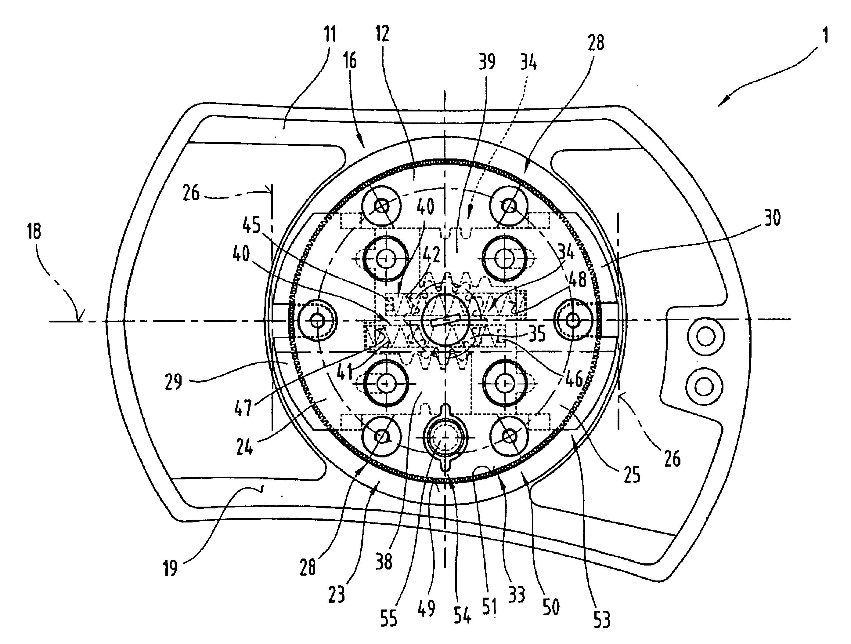
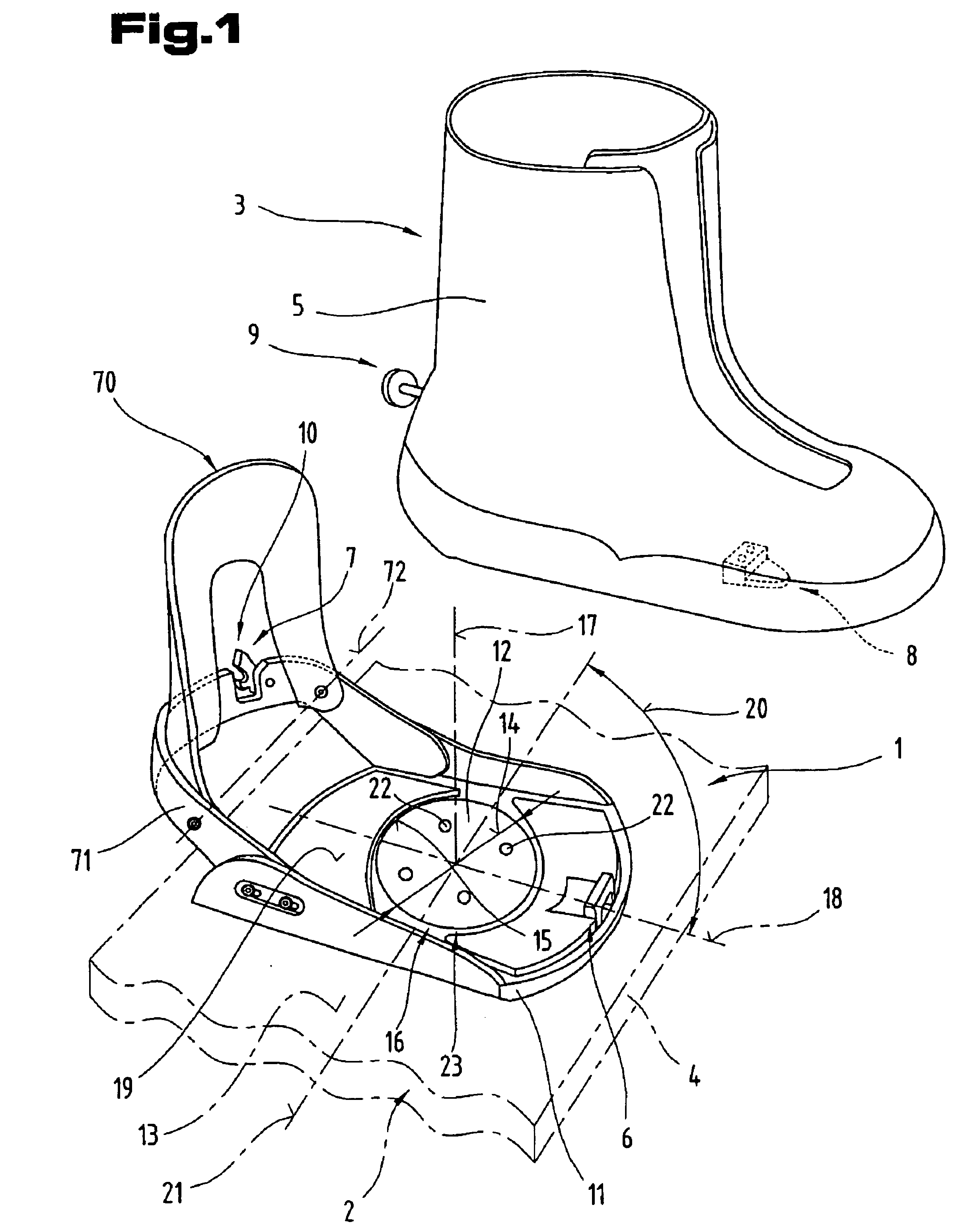
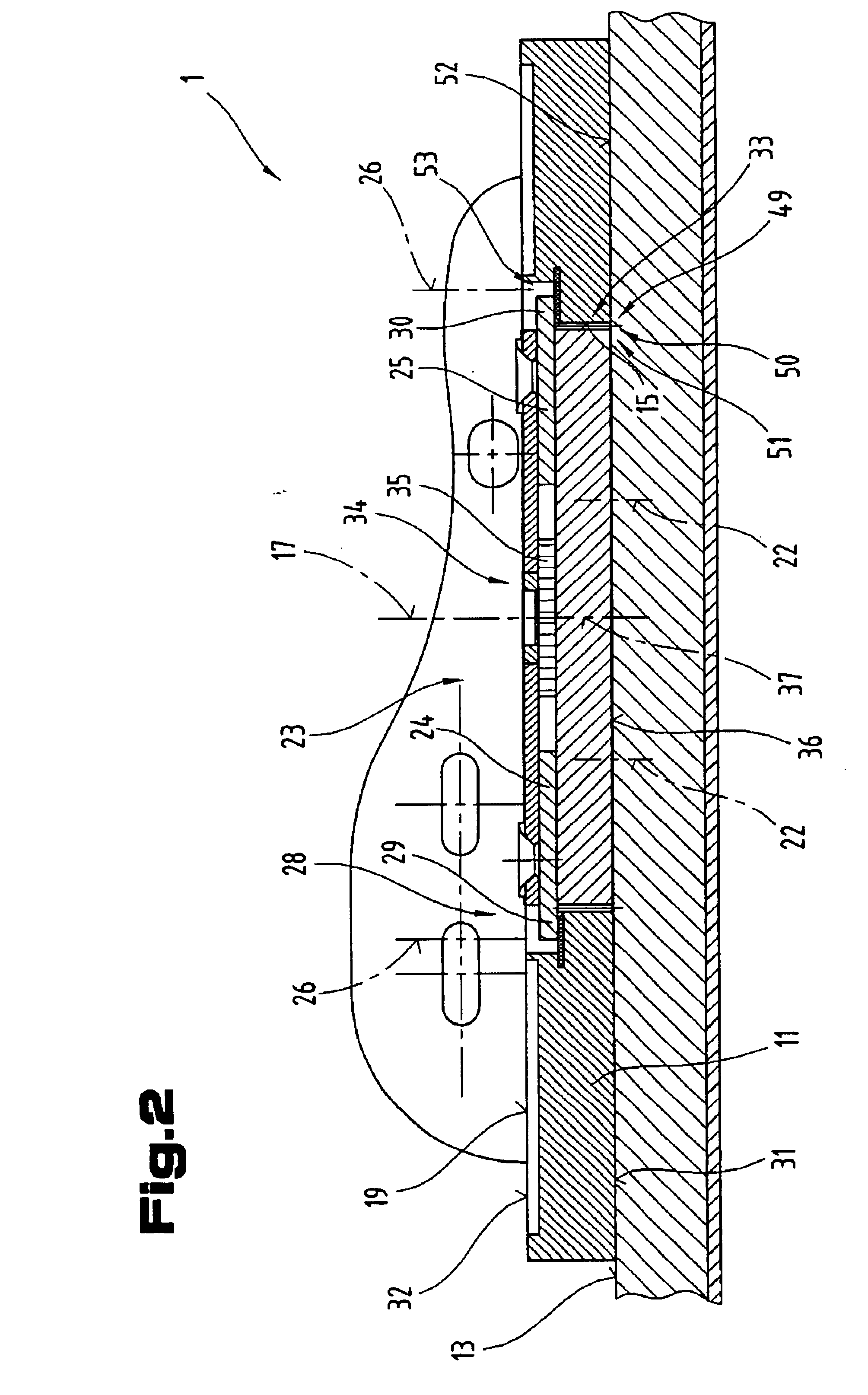
[0056]FIG. 1 is a perspective diagram of a binding unit 1 for connecting a gliding device, in particular a board-type sports device 2, to a sports shoe 3, so that it can be detached as necess...


PUM


Abstract

For the purpose of fixing a binding unit (1) to a snowboard (4), this binding unit (1) is provided with a retaining disc (12), which is substantially circular as seen in plan view, for a base plate (11) of relatively large surface area. Mounted on this base plate (11), either directly or indirectly, are coupling parts to provide a connection to a snowboard shoe. Teeth (49, 51) are provided between the base plate (11) and the retaining disc (12) inserted therein through a central orifice (15). The teeth (49, 51) securely fix selectively adjustable and fixable angular positions between the retaining disc (12) and the base plate (11). At least one slide element (24, 25) is provided on the retaining disc (12) and is displaceable between an extracted position (26), in which it spans or overlaps a transition region (28) between the retaining disc (12) and the base plate (11), and an inserted position, in which the slide element (24, 25) does not span or overlap this transition region (28). The slide element prevents the base plate from being lifted off the retaining disc in the extracted position while enabling it to be lifted off in the inserted position.

Description

BACKGROUND OF THE INVENTION[0001]1. Field of the Invention[0002]The invention relates to a binding unit for sports devices, in particular for a snowboard, which, for the purpose of fixing it to the sports device, is provided with a retaining disc, which is substantially circular as seen in plan view, for a base plate of relatively large surface area with coupling parts mounted directly or indirectly thereon to provide a connection to a sports shoe, in particular a snowboard shoe, which can be released as necessary, and having teeth between the base plate and the retaining disc inserted therein through a central orifice or corresponding recess, the purpose of the teeth being to securely fix selectively adjustable and fixable angular positions between the retaining disc and the base plate.[0003]2. The Prior Art[0004]Snowboard bindings which allow the angular position of the base plate relative to the circular retaining disc rigidly joined to the sports device to be adjusted are known ...

Claims


Application Information

Patent Timeline
Patent Type & Authority Patents(United States)
IPC IPC(8): A63C9/00A63C10/10A63C10/18A63C10/20A63C10/24
CPCA63C5/128A63C10/10A63C10/24A63C10/18A63C10/20A63C10/106
Inventor HOLZER, HELMUTLUITZ, MAX
Owner ATOMIC AUSTRIA
Why Eureka
Try Eureka