Fuel cell comprising a solid electrolyte layer

Inactive Publication Date: 2005-07-12
SULZER HEXIS AG
View PDF14 Cites 2 Cited by
  • Summary
  • Abstract
  • Description
  • Claims
  • Application Information

AI Technical Summary

Benefits of technology

[0008]2) The carrier structure is substituted by the inert material in a ring-shaped borde

Problems solved by technology

The first method is preferred, since the

Method used


Image

  • Fuel cell comprising a solid electrolyte layer
  • Fuel cell comprising a solid electrolyte layer
  • Fuel cell comprising a solid electrolyte layer

Examples


Example

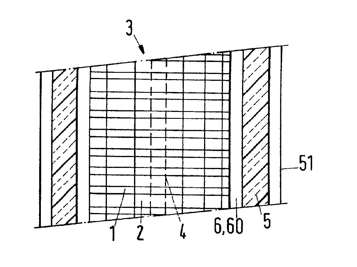
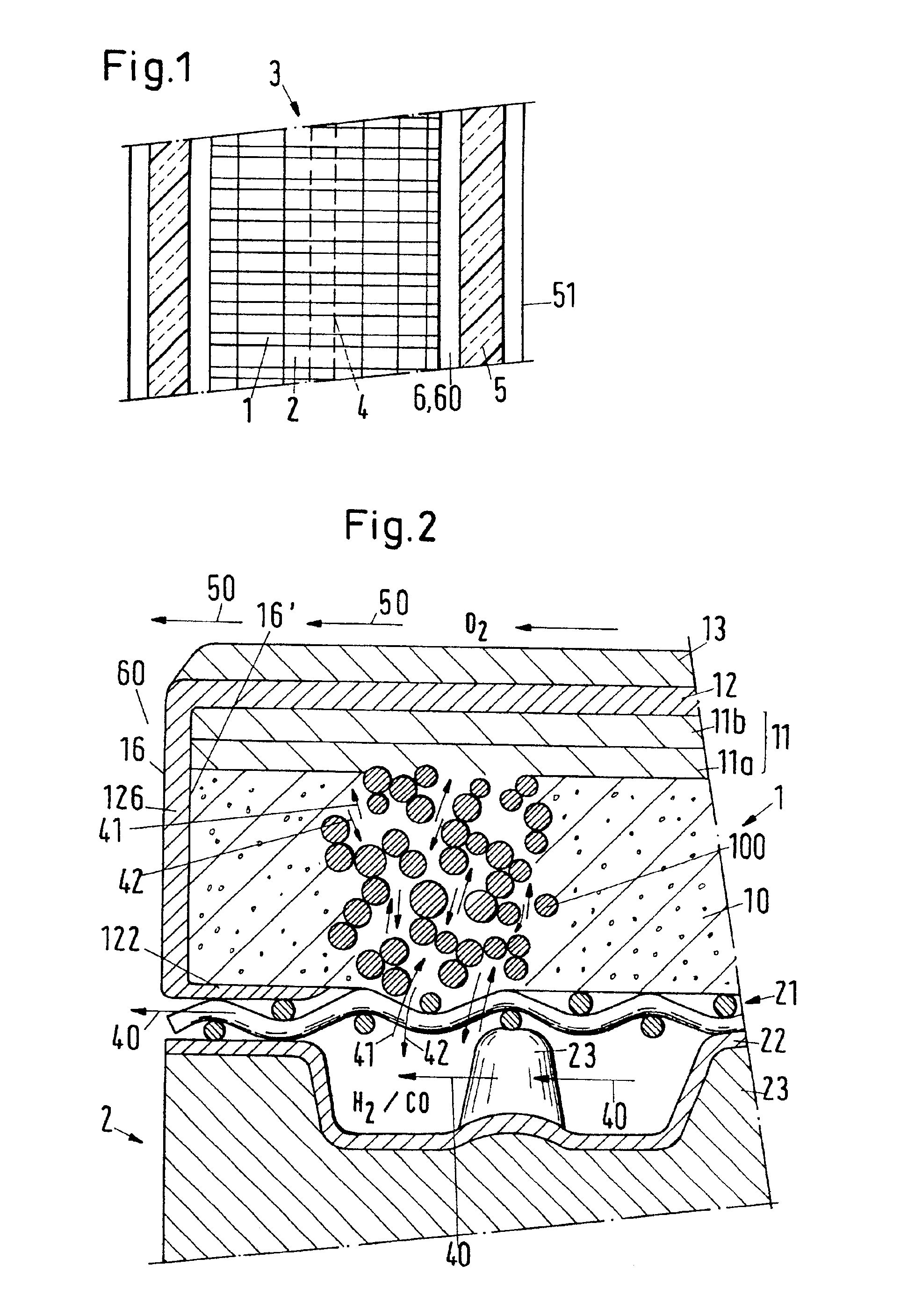
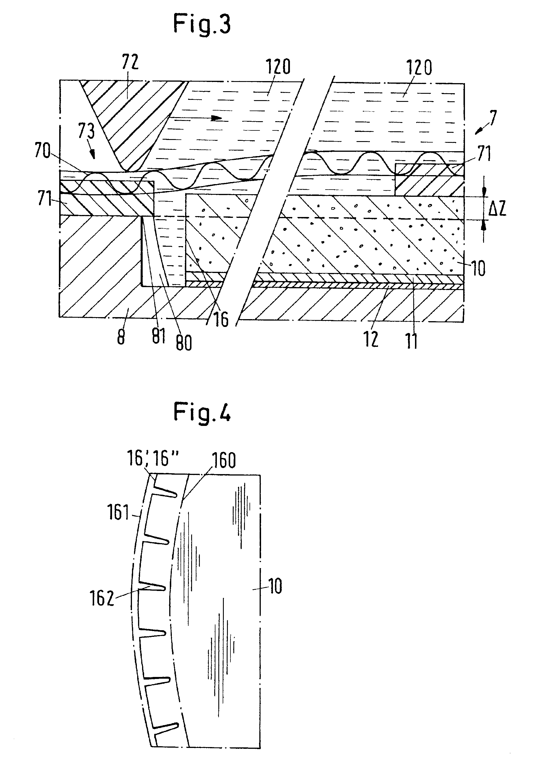
[0014]The battery which is schematically illustrated in FIG. 1 consists of a stack 3 of alternatingly arranged multiple layer plates 1 and interconnectors 2, which is shown in side view. The plates 1 are the electrochemically active constructional elements; the interconnectors 2 produce an electrical contact between adjacent cells. The interconnectors 2 are also formed as heat exchangers for preheating the gas flow which conducts oxygen; both of their surfaces carry a profiling which causes a largely uniform distribution of the oxidizing or reducing gas respectively over the multiple layer plate 1. The reducing gas is fed to the stack 3 via a central passage 4.

[0015]The cell stack 3 has in particular an axially symmetrical construction, which is for example circularly cylindrical or else prismatic. The stack 3 is surrounded by a heat insulating sleeve 5 and a ring space 6. Between an outer wall 51 and the sleeve 5 the oxidizing gas, i.e. the gas which contains the oxygen (as a rule ...


PUM


Abstract

A fuel cell having a solid electrolyte layer (12) forms together with two electrode layers (11, 13) a plate-like multiple layer system (1). The layers are applied by means of coating procedures to an open-pored, electrically conducting carrier structure (10) in the sequence anode (11), electrolyte (12) and cathode (13). This multiple layer system (1) has an outer edge which is exposed during a current generating operation of the fuel cell to an external environment (60) which contains molecular oxygen. The material of the carrier structure assumes an oxidized or a reduced state in thermodynamic equilibrium at the operating temperature of the fuel cell depending on the environment. The outer edge (16) of the multiple layer plate is covered over with an inert material. At the operating temperature of the fuel cell this edge covering (126) forms a barrier which inhibits or prevents the transport of molecular oxygen out of the external environment (60) into the carrier structure. The material is in particular YSZ, i.e. zirconium dioxide ZrO2 which is stabilized with yttrium oxide Y2O3.

Description

BACKGROUND OF THE INVENTION[0001]The invention relates to a fuel cell comprising a solid electrolyte layer and to a battery comprising fuel cells of this kind.[0002]High temperature fuel cells, the solid electrolyte of which is made in each case in the form of a thin layer as a part of a multiple layer plate, are known from EP-A-0 635 896 and EP-A-0 788 175. Thin-film electrolytes of this kind, which are 10-20 μm thick, can be applied to a carrier structure by means of a VPS process (Vacuum Plasma Spraying process). In addition to its mechanical function the carrier structure also has an electrochemical function as an electrode and an electrical function as a good conductor. In the so-called ASE cell (Anode Supported Electrolyte cell) the carrier structure is located on the side of the reducing fuel gas (H2, CO), i.e. on the anode side. The carrier structure can be manufactured of metallic felt, porous metallic foam or metal mesh. A suggestion of profiling metal structures of this k...

Claims


Application Information

Patent Timeline
IPC IPC(8): H01M8/02H01M8/24H01M8/12H01M8/0271H01M8/1231H01M4/86H01M8/124H01M8/2425
CPCH01M8/0271H01M8/1206H01M8/2425H01M2008/1293H01M2300/0074Y02E60/521Y02E60/525H01M8/1231Y02E60/50H01M8/2432H01M8/10H01M8/02
Inventor BATAWI, EMADHONEGGER, KASPAR
Owner SULZER HEXIS AG
Why Eureka
Try Eureka