
Flow-through sampling cell and use thereof

Inactive Publication Date: 2001-02-27
GYROS
View PDF10 Cites 77 Cited by
  • Summary
  • Abstract
  • Description
  • Claims
  • Application Information

AI Technical Summary

Benefits of technology

The present invention relates to a sampling cell of flow-through type, i.e. a sampling cell with at least one flow inlet and at least one flow outlet from which samples are extracted from at least one sample emerging orifice, this orifice being separated from the flow inlet and the flow outlet. A sampling cell of flow-through type thus differs from other sampling cells, of non flow-through types, such as those wherein the flow outlet also serves as sample emerging orifice.
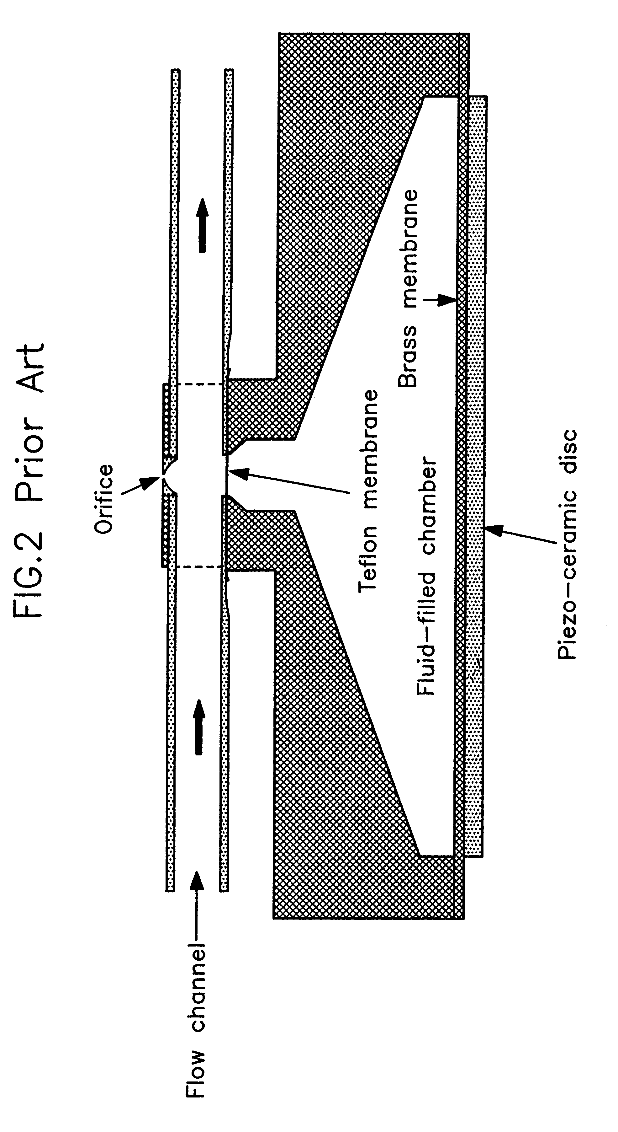
The above described tool for micro sampling according to Ref. 1 has some disadvantages, such as transmission of the pressure pulse through an intermediate chamber and through two separate membranes, rather large dead volumes, risk for sticking of pressure pulse absorbing bubbles within the tool due to the hollow part adjacent the orifice type nozzle, low resonance frequency due to the large overall dimensions of the tool, adherence of liquid to the area around the exit side of the orifice type nozzle, need for separate filling of the conical fluid-filled chamber, need for regular exchange of the teflon membrane, requirements for t

Problems solved by technology

The sample extration and the fraction determination are tedious procedures, often including test tube matrix handling followed by analysis through e.g. gel electrophoresis before a final fraction identification is achieved.
Anyhow this device is not of the flow-through type and can not be used for extracting samples from a continuous flow.
The above described tool for micro sampling according to Ref. 1 has some disadvantages, such as transmission of the pressure pulse through an intermediate chamber and through two separate membranes, rather large dead volumes, risk for sticking of pressure pulse absorbing bubbles within the tool due to the hollow part adjacent the orifice type nozzle, low resonance frequency due to the large overall dimensions of the tool, adherence of liquid to the area around the exit side of the orifice type nozzle, need for separate filling of the conical fluid-filled chamber, need for regular exchange of the teflon membrane, requirements for tightening around the teflon membrane, and comparably complicated and expensive manufacturing.
Furthermore the method is limited to ejection of small liquid volumes through heating and subsequent evaporation of the liquid.
Such heating may destroy the characteristics of the liquid.

Method used


Image

  • Flow-through sampling cell and use thereof
  • Flow-through sampling cell and use thereof
  • Flow-through sampling cell and use thereof

Examples


example 2

A sampling cell essentially in accordance with Example 1 was used in the following. A glass capillary for capillary electrophoresis was filled with a solution of sodium chloride (NaCl). Through a first end of the capillary was introduced a thin electrically conducting wire for contacting the solution. The second end of the capillary was placed close to the sampling cell, which was filled with ordinary tap water, and subsequently with a sodium chloride solution which did not alter the below described effects. The drop generation was initiated with a drop emerging frequency of around 50 Hz. A high voltage source was connected to the liquid in the sampling cell and to the wire in the first end of the glass capillary. A voltage of about 2500 V was used. When the voltage was applied the emerging drops were attracted by the second end of the glass capillary. The drops did hit the second end surface of the capillary and the outside of the capillary just below this second end surface. By al...


PUM


Abstract

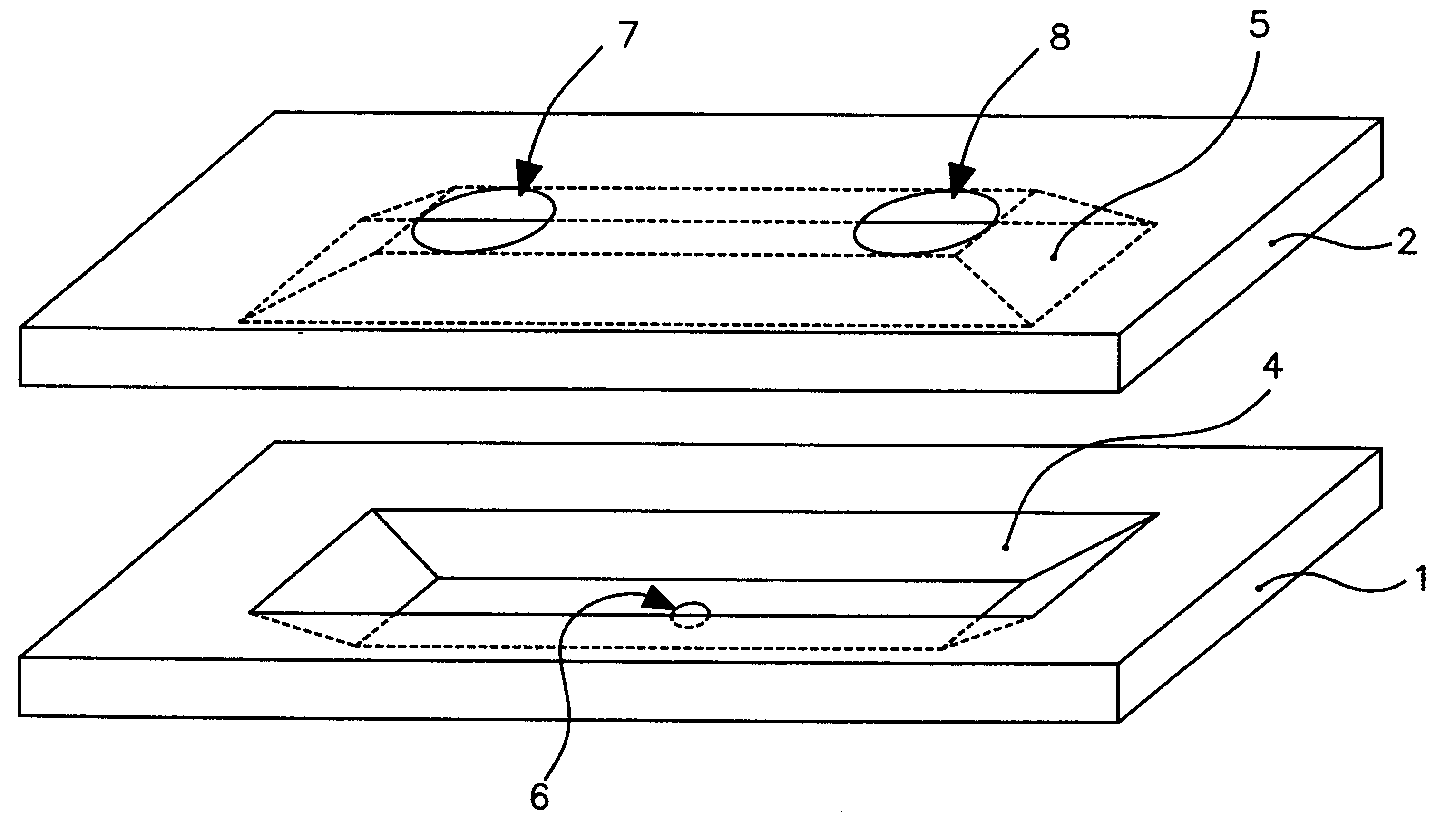
A sampling cell of flow-through type and use of such a sampling cell. The sampling cell is preferably manufactured by etching of silicon wafers. It is especially useful for continuous picovolume sampling in an analytical flow. The pressure pulse generator (9) generates pulses directly into a flow channel (3). The flow channel (3) is preferably formed by a first basin (4) in a first structure (1) and a second basin (5) in a second structure (2). In a first embodiment the pressure pulse generator (9) comprises at least one piezo-ceramic disc and / or devices acting by way of magnetostrictive, electrostatical or electromechanical forces and / or devices acting by way of thermal expansion. Method of directing samples from a flow-through sampling cell by establishing a difference in electrical potential between the liquid in the flow-through sampling cell and the object to which the samples are to be directed. Use of a flow-through sampling cell for coating of surfaces, especially for achieving biospecific surfaces, for extracting samples from a continuous liquid flow, for extracting a precise sample amount by collecting a defined number of samples or for injecting samples for electrophoresis, especially capillary electrophoresis, and for electrochromatography.

Description

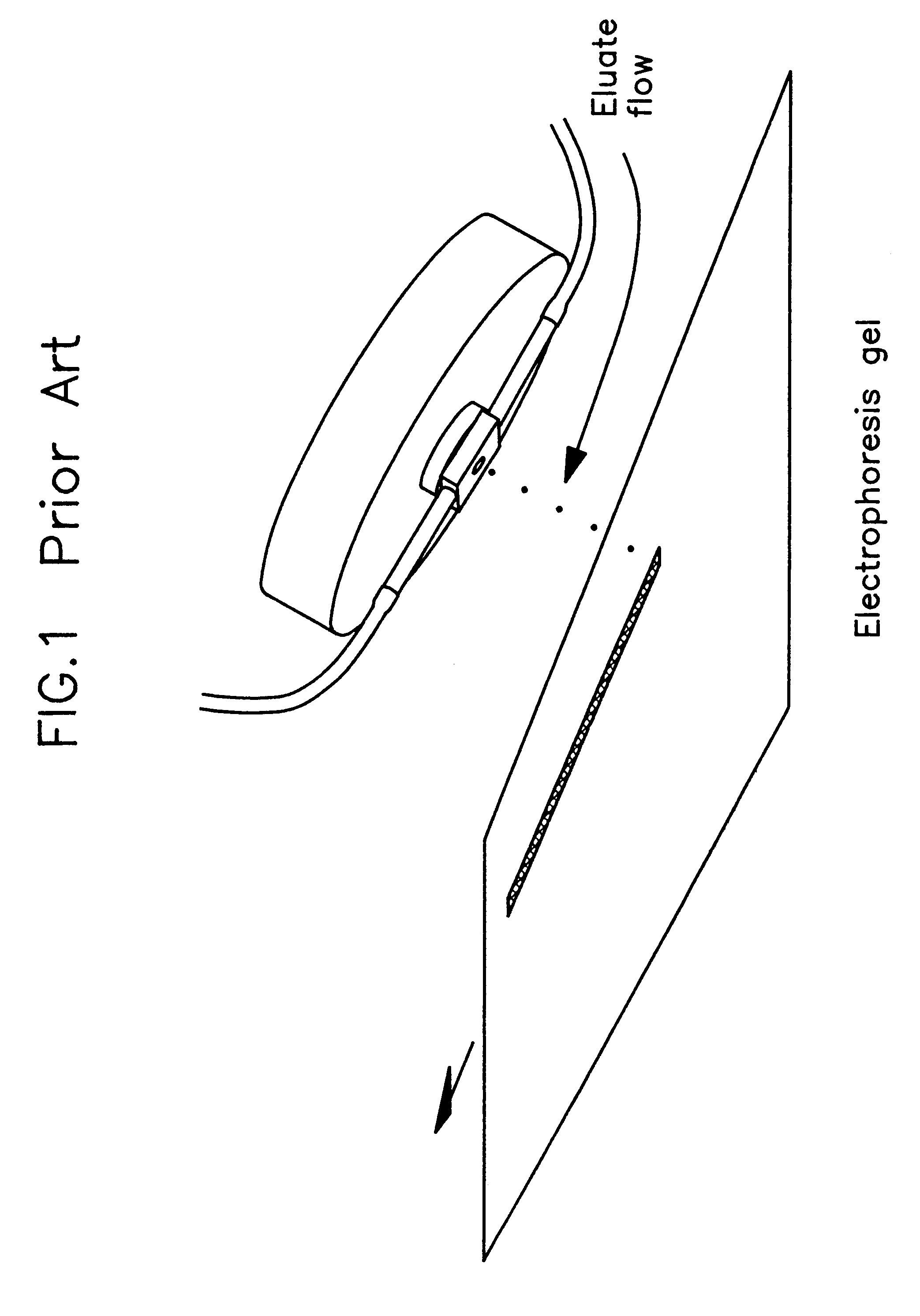
This invention relates to a sampling cell of flow-through type, a method for directing samples from such a sampling cell and use of such a sampling cell. The sampling cell is preferably manufactured by etching of silicon wafers. It is especially useful for continuous picovolume sampling in an analytical flow or for picovolume deposition of specific chemicals.1. Background and Prior ArtMicro sample extraction is useful in e.g. fraction determination from protein separation systems. The sample extration and the fraction determination are tedious procedures, often including test tube matrix handling followed by analysis through e.g. gel electrophoresis before a final fraction identification is achieved.Ref. 1 discloses a known sampling tool for fraction identification, being a flow-through cell comprising an orifice type nozzle and a piezo-ceramic disc glued onto a brass membrane. The brass membrane bends when a voltage is applied across the piezo-ceramic disc. The bending brass membra...

Claims


Application Information

Patent Timeline
IPC IPC(8): B01L3/02B01L3/00G01N1/10B01F13/00G01N30/28G01N30/00G01N30/16G01N35/10G01N35/00G01N27/62G01N1/00G01N27/447
CPCB01F15/0241B01F15/0255B01L3/0268B01L3/502715G01N1/10B01F13/0059B01L2200/0605B01L2400/0439B01L2400/0487G01N2030/162G01N2030/285G01N2035/00237G01N2035/1041B01F33/30B01F35/717551B01F35/71791
Inventor WALLMAN, LARSDROTT, JOHANNILSSON, JOHANLAURELL, THOMASNILSSON, STAFFAN
Owner GYROS
Learn More