System and method for controlling output-timing parameters of power converters

a power converter and output-timing technology, applied in the direction of electric variable regulation, process and machine control, instruments, etc., can solve the problems of increasing complexity, expense and size of the control system, and inability to deliver high current at low voltage levels

Inactive Publication Date: 2005-08-30
BEL POWER SOLUTIONS INC
View PDF24 Cites 80 Cited by
  • Summary
  • Abstract
  • Description
  • Claims
  • Application Information

AI Technical Summary

Benefits of technology

[0008]The present invention provides a system and method of utilizing output-timing data to control at least one output timing parameter of a point-of-load (“POL”) regulator. Embodiments of the present invention operate in accordance with a power supply controller (“controller”) and at least one POL regulator. Specifically, in one embodiment of the present invention, each POL regulator includes an output builder, a control unit and a storage device. In this embodiment, the controller is adapted to transmit output-timing data to the regulator via a bus, or more particularly to the control unit (e.g., microprocessor, etc.) located within the POL regulator. The output-timing data is then stored in the storage device and used by the control unit and the output builder (e.g., voltage generating device, etc.) to produce an output.

Problems solved by technology

This is problematic in that it is impractical to deliver high current at low voltage levels over a relatively long distance and still meet desired regulation performances.
The drawback with such a control system is that it adds complexity, expense and size to the control system by requiring the controller to communicate with multiple devices (e.g., a POL regulator and an external transistor switch) to control the output timing parameters of a single POL regulator.

Method used


Image

  • System and method for controlling output-timing parameters of power converters
  • System and method for controlling output-timing parameters of power converters
  • System and method for controlling output-timing parameters of power converters

Examples


Embodiment Construction

[0017]The present invention provides a system and method of utilizing output-timing data to control at least one output timing parameter of a POL regulator. In the detailed description that follows, like element numerals are used to describe like elements illustrated in one or more figures.

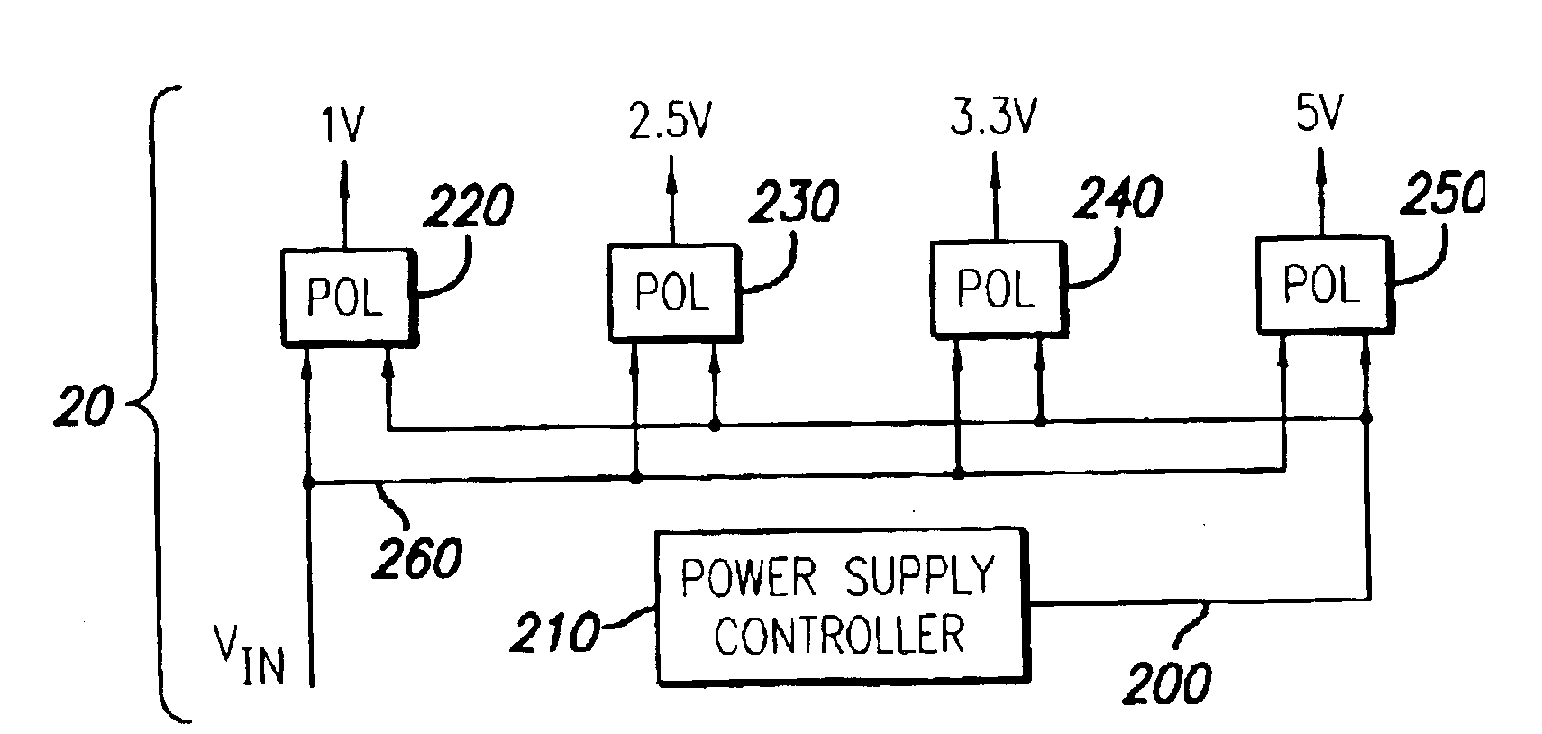
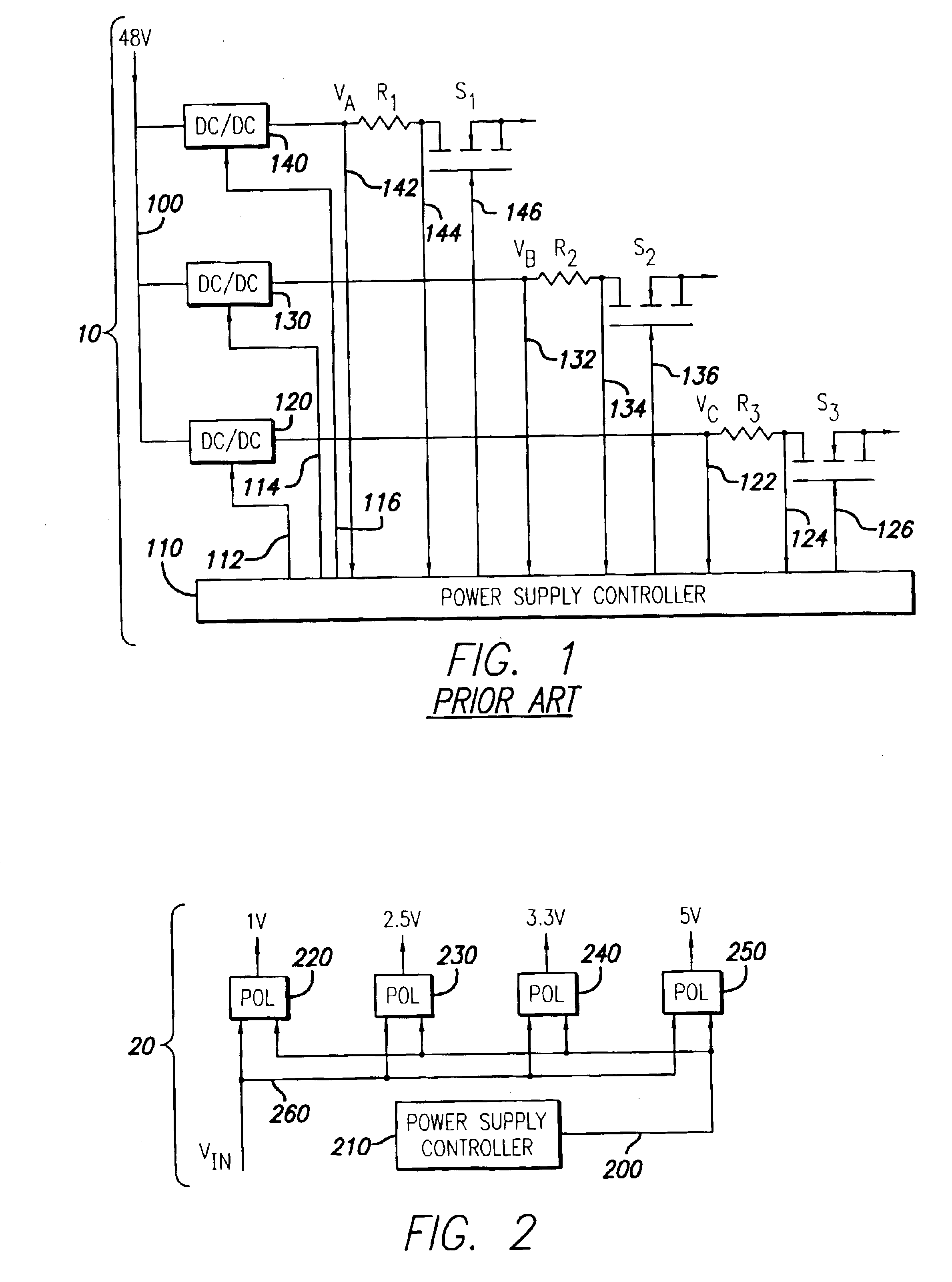
[0018]FIG. 1 illustrates a prior art DC / DC control system 10 where the power supply controller (“controller”) 110 communicates with a plurality of DC / DC converters (i.e., 120, 130 and 140), also referred to as voltage regulators or POL regulators, via a plurality of six bit parallel buses (i.e., 112, 114 and 116), and a plurality of external circuits (e.g., R1 / S1, R2 / S2, R3 / S3) via a plurality of three-wire output connections (i.e., 122-126, 132-136, and 142-146). More particularly, each six bit parallel bus includes an enable / disable bit and five VID code bits, and each three-wire output connection includes a voltage monitoring line (i.e., 122, 132 and 142), a current monitoring line (i.e., 124, ...


PUM


Abstract

A system and method is provided for utilizing output-timing data to control at least one output timing parameter of a point-of-load (“POL”) regulator. Specifically, a power supply controller (“controller”) is adapted to transmit output-timing data to at least one POL regulator. In one embodiment of the present invention, each POL regulator includes an output builder, a control unit and a storage device. The control unit is adapted to store the output-timing data in the storage device. The control unit and the output builder are then adapted to produce an output having at least one output timing parameter in accordance with the output-timing data. Examples of output-timing data include sequencing data, turn-on data, turn-off data, termination data, slew-rate data, etc. For example, a POL regulator may be adapted to utilize output-timing data, or a portion thereof (e.g., slew-rate data), to generate an output having a particular slew rate. Similarly, a POL regulator may be adapted to utilize output-timing data, or a portion thereof (e.g., sequencing data, turn-on data, etc.), to determine (or calculate) a period of time to wait (e.g., delay period) before the output is generated. In other words, output-timing data can be used to produce a series of outputs in a particular order, or sequence.

Description

BACKGROUND OF THE INVENTION[0001]1. Field of the Invention[0002]The present invention relates to controlling a point-of-load (“POL”) regulator output, or more particularly, to a system and method of utilizing output-timing data to control at least one output timing parameter of a POL regulator.[0003]2. Description of Related Art[0004]Point-of-load (“POL”) regulators, which are also referred to as voltage regulators or DC / DC converters, are commonly used in conjunction with electronic circuits. This is because the voltage / current requirements of electronic circuits typically differ from the voltage that is readily available or the current that can practically be delivered. For example, some electronic devices only include a single voltage input (e.g., 12v), but require different voltages for circuits contained within (e.g., 3v, 5v, 9v, etc.). A common solution is to design multiple POL regulators within the device for converting the single input voltage into multiple voltage levels.[...

Claims


Application Information

Patent Timeline
Patent Type & Authority Patents(United States)
IPC IPC(8): H02J1/08
CPCH02J1/08H02M1/08H02J2001/008H02M2001/008H02J1/082H02M1/008H02M3/156
Inventor CHAPUIS, ALAIN
Owner BEL POWER SOLUTIONS INC
Why Eureka
Try Eureka