Electric motor with self-adjusting bushing structure

a technology of electric motors and bushings, which is applied in the direction of sliding contact bearings, gearing details, gearing, etc., can solve the problems of conventional motors that require many parts and require many parts, and require many endplay plates of different thicknesses, so as to prevent motor lockup

Active Publication Date: 2005-11-15
BROSE FAHRZEUGTEILE GMBH & CO KG HALLSTADT (DE)
View PDF15 Cites 14 Cited by
  • Summary
  • Abstract
  • Description
  • Claims
  • Application Information

AI Technical Summary

Benefits of technology

[0005]An object of the present invention is to fulfill the need referred to above. In accordance with the principles of the present invention, this objective is obtained by providing a bushing structure constructed and arranged to be operatively associated with a shaft of an electric motor. The motor has a housing including a generally elliptical recess therein defined along an axis of the shaft. The bushing structure includes a generally cylindrical bushing member constructed and arranged to engage an end of the shaft so as to locate the shaft with respect to the housing and to prevent lockup of the motor. An endplay member is associated with the bushing member and with the end of the shaft. The endplay member includes a spherical portion constructed and arranged to be received in the elliptical recess so as to control endplay of the shaft.

Problems solved by technology

Disadvantages of this configuration include the requirement of providing numerous parts (endplay plates) with different thickness.
Thus, conventional motors require numerous parts with regard to controlling shaft location and endplay.

Method used


Image

  • Electric motor with self-adjusting bushing structure
  • Electric motor with self-adjusting bushing structure
  • Electric motor with self-adjusting bushing structure

Examples


Embodiment Construction

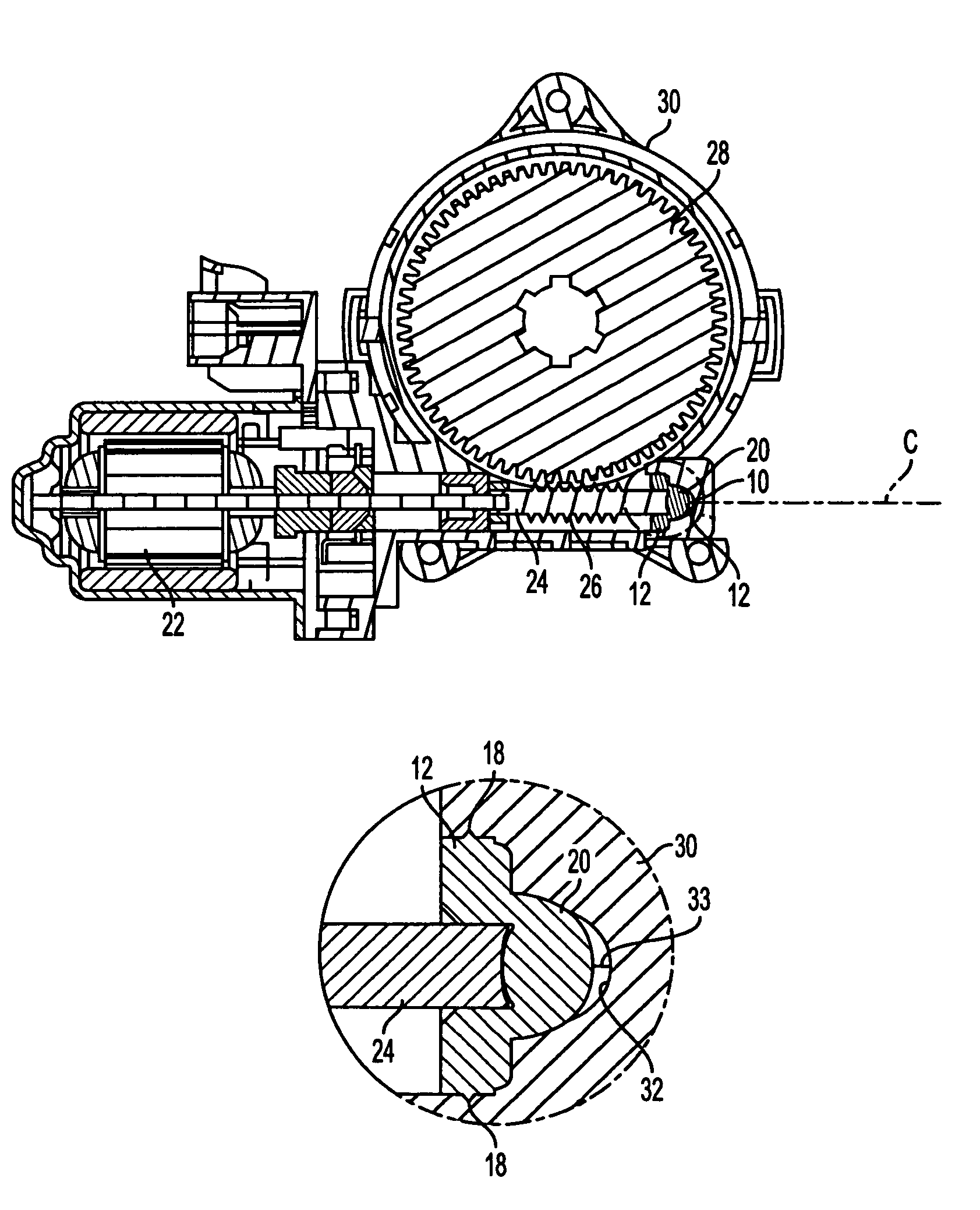
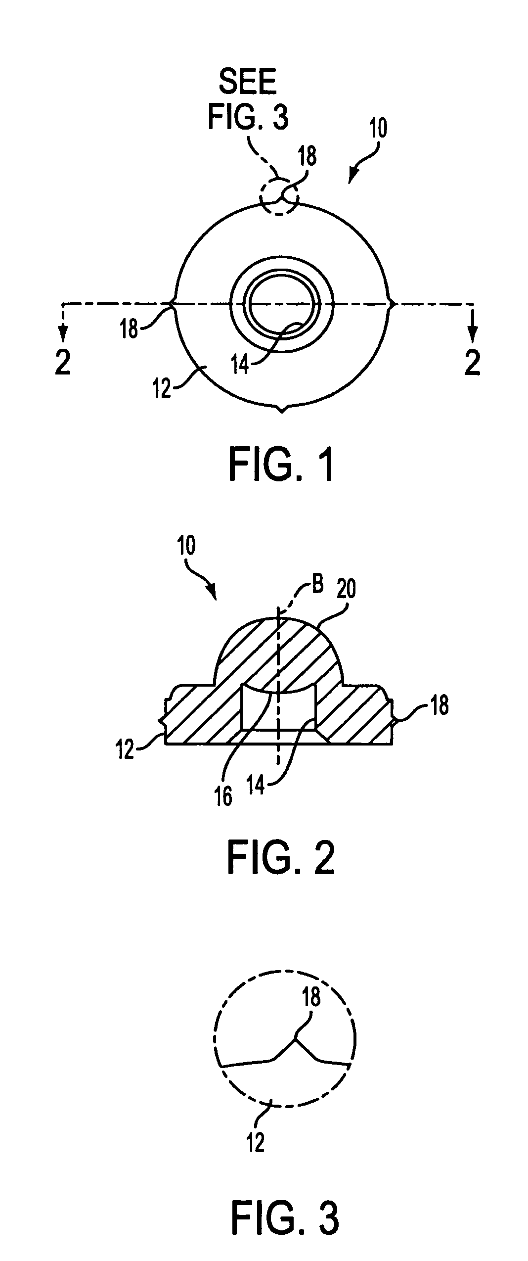
[0015]With reference to FIGS. 1–3, a self-adjusting cylindrical bushing structure is shown, generally indicated at 10, in accordance with the invention. The bushing structure 10 includes a generally cylindrical bushing member 12 having a central axis B. The bushing member 12 includes a recess 14 therein extending along the axis B and constructed and arranged to receive an end of a rotatable shaft 24 of a motor 22 (FIG. 4). The motor 22 is preferably a bidirectional windowlift motor for a vehicle. A bottom of the recess includes a curved portion 16 that engages the shaft end. The bushing member 14 also includes a plurality of protrusions 18 extending outwardly from a periphery thereof, the function of which will be explained below. An endplay member 20 in the form of a generally half-sphere, is integral with and extends from the bushing member 12.

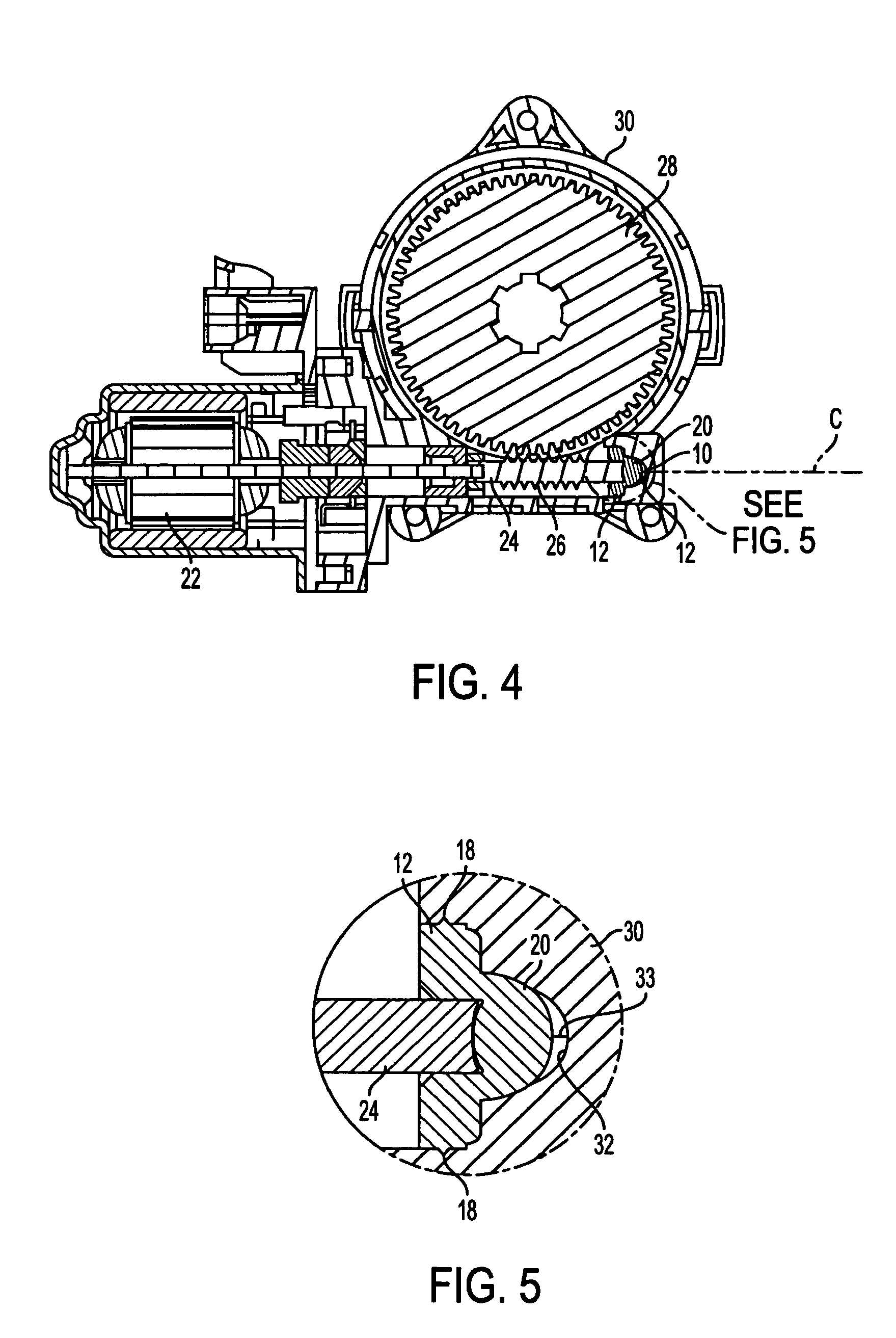
[0016]The bushing structure 10 is shown in FIG. 4 incorporated into an electric motor 22 with a shaft 24 having a worm 26 associated with a...


PUM


Abstract

A bushing structure 10 is constructed and arranged to be operatively associated with a shaft 24 of an electric motor 22. The motor has a housing 30 including a generally elliptical recess 32 therein defined along an axis C of the shaft. The bushing structure includes a generally cylindrical bushing member 12 constructed and arranged to engage an end of the shaft so as to locate the shaft with respect to the housing and to prevent lockup of the motor. An endplay member 20 is associated with the bushing member and with the end of the shaft. The endplay member includes a spherical portion constructed and arranged to be received in the elliptical recess so as to control endplay of the shaft.

Description

[0001]This application is based on U.S. Provisional Application No. 60 / 520,015, filed on Nov. 14, 2003 and claims the benefit thereof for priority purposes.FIELD OF THE INVENTION[0002]This invention relates to controlling endplay and alignment of a shaft of an electric motor.BACKGROUND OF THE INVENTION[0003]In conventional motors, one of a number of endplates is selected to take-up a gap between an end of a shaft and a gear housing. The endplay plates vary in thickness by 0.1 mm. Visual inspection is done to optimize the gap and the correct thickness endplay plate is picked up via automation to meet the constant endplay plate gap of between 0.02–0.20 mm. Disadvantages of this configuration include the requirement of providing numerous parts (endplay plates) with different thickness. In addition, a constant process check is needed to select the optimum endplay plate 10 based on the gap between the end of the shaft 12 and endplay plate 10. Furthermore, with these configurations, a sep...

Claims


Application Information

Patent Timeline
Patent Type & Authority Patents(United States)
IPC IPC(8): H02K7/08F16C17/08F16H1/16F16H57/02
CPCF16C17/08F16H57/021H02K7/081F16H1/16F16H2057/0221F16H2057/0213F16C2380/27F16C2361/61H02K7/08
Inventor OH, JONYEONREE, ROLANDANDERSON, BARRY
Owner BROSE FAHRZEUGTEILE GMBH & CO KG HALLSTADT (DE)
Why Eureka
Try Eureka