Apparatus for reducing the power consumption of a PFC-PWM power converter

a power converter and power consumption technology, applied in the direction of electric variable regulation, process and machine control, instruments, etc., can solve the problems that traditional power converters often fail to meet government-mandated power conservation requirements, and the internal consumption of substantial amounts of pfc circuits is not easy to achieve. achieve the effect of reducing the power consumption of a pfc-pwm power converter

Active Publication Date: 2005-11-22
SEMICON COMPONENTS IND LLC
View PDF5 Cites 89 Cited by
  • Summary
  • Abstract
  • Description
  • Claims
  • Application Information

AI Technical Summary

Benefits of technology

[0007]The present invention provides an apparatus for reducing the power consumption of a PFC-PWM power converter. The apparatus according to the present invention includes a PFC power-manager and a PWM power-manager. The apparatus also includes a control terminal applied to detect the line-input voltage and control a PFC signal and a PWM signal.
[0010]The PFC power-manager controls the output voltage of the PFC boost converter in response to the voltage range of the line-input. This enables the PFC-PWM controller to optimize the efficiency of the PFC boost converter and reduce power consumption under full-load conditions.
[0011]During low-voltage line-input conditions, such as brownouts, the PFC power-manager and the PWM power-manager will disable the PFC boost converter and the DC-to-DC power converter. This protects the PFC circuitry from over-stress operation and saves power. In addition, the PWM power-manager will disable the PFC boost converter during low-load conditions, to further reduce the power consumption of the power converter.

Problems solved by technology

Unfortunately, traditional PFC circuits internally consume substantial amounts of power.
Because of this, traditional power converters often fail to meet government-mandated power conservation requirements.

Method used


Image

  • Apparatus for reducing the power consumption of a PFC-PWM power converter
  • Apparatus for reducing the power consumption of a PFC-PWM power converter
  • Apparatus for reducing the power consumption of a PFC-PWM power converter

Examples


Embodiment Construction

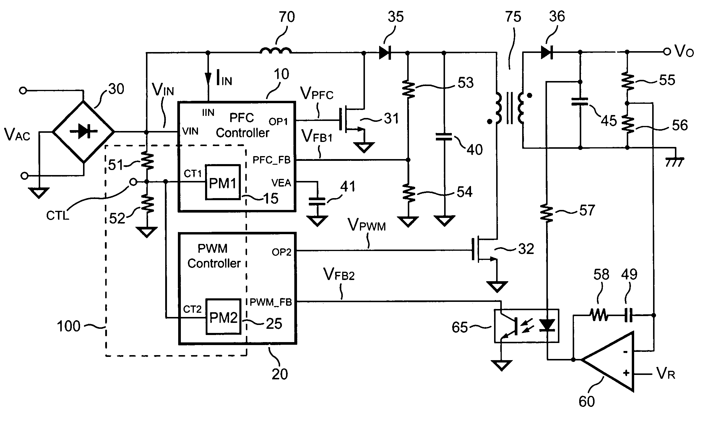
[0019]FIG. 1 shows a schematic circuit diagram of a PFC-PWM power converter according to a preferred embodiment of the present invention. According to the present invention, an apparatus 100 is included to reduce the power consumption of the PFC-PWM power converter. The PFC-PWM power converter includes a PFC controller 10. The PFC controller 10 includes a line-voltage input terminal VIN, a line-current input terminal IIN, a PFC-control terminal CT1, a compensation terminal VEA, a PFC output terminal OP1, and a feedback input terminal PFC—FB. The line-voltage input terminal VIN is used to detect the line-input voltage information. The line-current input terminal IIN is applied to detect the line-input current information.

[0020]The PFC-PWM power converter includes a PFC boost converter. The PFC boost converter comprises an inductor 70, a rectifier 35, a switching device 31, and a capacitor 40. The PFC boost converter produces a PFC output voltage across the capacitor 40. The PFC boost...


PUM


Abstract

An apparatus for reducing the power consumption of a PFC-PWM power converter is described. The apparatus includes a control terminal used to detect a line-input voltage and to control a PFC signal and a PWM signal. The apparatus further includes a PFC power-manager and a PWM power-manager. The PFC power-manager of the PFC controller determines a PFC-reference voltage for an error amplifier of the PFC controller. The PFC-reference voltage is generated in response to the voltage at the control terminal. The PFC power-manager will disable the PFC signal whenever the voltage at the control terminal drops below a low-voltage threshold voltage. The PWM power-manager will disable the PWM signal whenever the voltage at the control terminal drops below a programmable threshold voltage. Furthermore, the PWM power-manager will pull the voltage at the control terminal low to disable the PFC circuitry during light-load and zero-load conditions.

Description

BACKGROUND OF THE INVENTION[0001]1. Field of the Invention[0002]The present invention generally relates to the art of switching mode power converters. More particularly, the present invention relates to PFC-PWM power converters.[0003]2. Description of Related Art[0004]Many power converters apply power factor correction (PFC) to correct the line current and subsequently generate a sinusoidal input current waveform that is in phase with the line voltage. Adding a PFC circuitry to the front end of a DC-to-DC power converter can prevent unnecessary power loss and heat dissipation from occurring in the power distribution system.[0005]Unfortunately, traditional PFC circuits internally consume substantial amounts of power. This is especially significant under light-load and zero-load conditions. Because of this, traditional power converters often fail to meet government-mandated power conservation requirements.[0006]The objective of the present invention is to provide an apparatus to reduc...

Claims


Application Information

Patent Timeline
Patent Type & Authority Patents(United States)
IPC IPC(8): G05F1/10H02M3/28H02M7/00H02M3/335H02M3/24H02M1/42
CPCH02M1/4208H02M2001/0025H02M2001/0032Y02B70/126Y02B70/16Y02B70/10Y02P80/10H02M1/0025H02M1/0032
Inventor YANG, TA-YUNGHSUEH, CHENG-CHI
Owner SEMICON COMPONENTS IND LLC
Why Eureka
Try Eureka