Paper clip

a paper clip and clip technology, applied in the field of paper clips, can solve the problems of difficult plastic manufacturing of 823, poor paper clip management in the prior arts, and difficulty in u.s. tie clasps, etc., and achieve the effect of variable capacity

Inactive Publication Date: 2005-12-13
HSIAO RAY LING
View PDF25 Cites 22 Cited by
  • Summary
  • Abstract
  • Description
  • Claims
  • Application Information

AI Technical Summary

Benefits of technology

[0012]The first object of the present invention is to offer an improved paper clip to have a function for clamping thicker documents. The present invention supplies a capacity for storing thicker documents, and also the thickness of the capacity is variable, thus the present invention can be widely applied on paper work.
[0013]The second object of the present invention is to offer an improved paper clip to have a function for enough clamping force to even one piece of paper.

Problems solved by technology

Therefore, the prior arts as mentioned above are not good enough to manage the present paper work operations.
Such kind of structure makes the tie clasp of U.S. Pat. No. 3,950,823 difficult to be manufactured by plastic ejection, since the overlapped portions of the tie clasp makes it extremely difficult to be taken off from the molds along the top-view direction during the plastic ejecting process.
As the result, the tie clasp of U.S. Pat. No. 3,950,823 suffers the deficiency of being difficult to be made by plastic ejection.
If this back portion is not large enough, then the effective connection between the support panel and the curved clip will be only at the two ends of the bottom edge and will be prone to break easily.
The leading edges of documents cannot be stacked straightly.
Thus the appearance of the holder would be ugly when holding documents.
The amount of documents which this paper clip can hold is thus limited.
The paper clip disclosed by U.S. Pat. No. 5,704,724 is not suitable for holding lots of documents with significant thickness.
It fails to provide an integral and beautiful appearance to the clip and the documents.

Method used


Image

  • Paper clip
  • Paper clip
  • Paper clip

Examples


Embodiment Construction

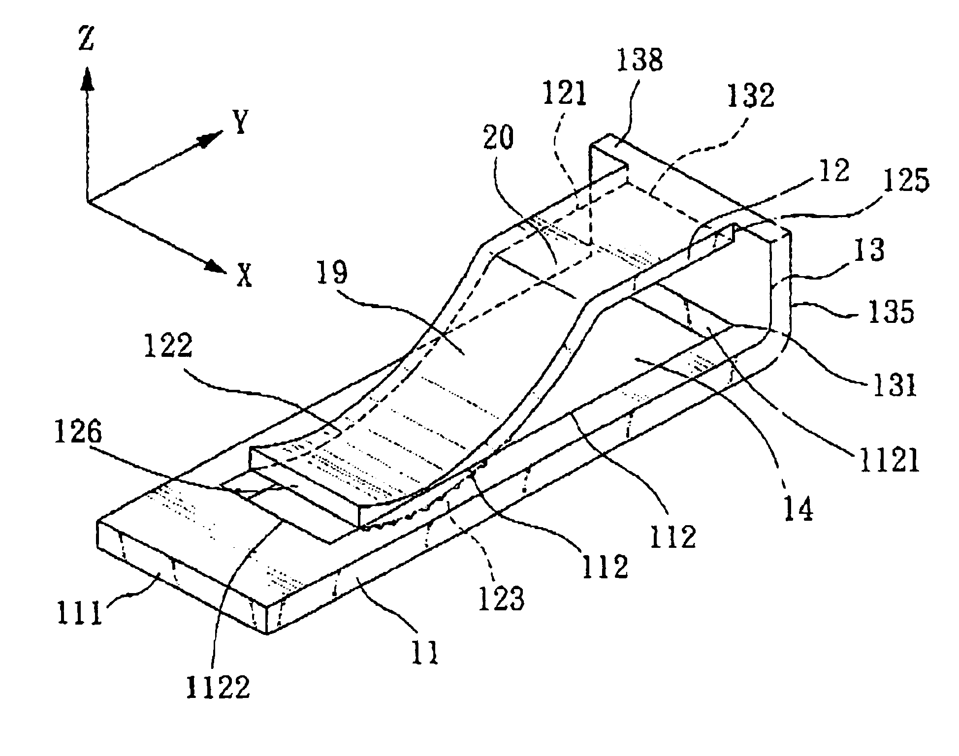
[0029]Referring to FIG. 4, which is the 3-dimension view of the first preferred embodiment of the present invention. The improved paper clip is made of plastic or steel. A first clipping piece 11 with thin plane shape for placing document is almost parallel to a top surface 121 of a horizontal part 20 of a second clipping piece 12, and which is a lower part of the paper clip of the first preferred embodiment. The second clipping piece 12 with thin plane shape is an upper part of the paper clip of the first preferred embodiment. The first clipping piece 11 is larger than the second clipping piece 12 in both length directions (i.e., the “Y” direction indicated in FIG. 4) and width direction (the “X” direction shown in FIG. 4). The support beam 13 is substantially a vertical plate for connecting with both the first and second clipping pieces 11, 12. The first clipping piece 11 connects to a first connecting portion 131 (also referred as connected end hereinafter) located at the two sid...


PUM


Abstract

The present invention relates to an improved paper clip which is suitable for holding documents of different thicknesses. The improved paper clip includes three elements, which are a first clipping piece, a second clipping piece and a support beam. The first clipping piece is formed with a sunken slot therethrough and is connected to a bottom side of the support beam. The second clipping piece has a bending curve part and is connected to a top side of the support beam. The bending curve part is partially protruding into the sunken slot and is roughened to become a rough surface for increasing friction to tightly clamp documents. The inner surface of the support beam is a flat plane so as to provide a guiding function when the document is received between the first and second clipping pieces. The first and second clipping pieces are both adjoined to the inner surface of the support beam, such that the outer surface of the support beam substantially forms part of the outer contour of the paper clip.

Description

CROSS-REFERENCE TO RELATED APPLICATION[0001]This application is a continuation-in-part of U.S. patent application Ser. No. 10 / 002,204 filed on Dec. 5, 2001 now abandoned.FIELD OF THE INVENTION[0002]The present invention is an improved paper clip; especially it is for clamping different thicknesses of documents.BACKGROUND OF THE INVENTION[0003]Traditionally, most kinds of paper clips are made of steel wires. It is very convenient for clipping documents and especially for papers. Referring to FIG. 1, which is the 3-dimension view of prior art and normally made of plastic, because plastic is a flexible material. A bottom surface of paper 4 is put on first clipping piece 1, and second clipping piece 2 is above a top surface of paper 4, which means paper 4 is within the first clipping piece 1 and the second clipping paper 2. Top edge 40 is against to joint place 3, thus the paper 4 can be clamped tightly. The first clipping piece 1 and the second clipping piece 2 are located at the same ...

Claims


Application Information

Patent Timeline
Patent Type & Authority Patents(United States)
IPC IPC(8): B42F1/02
CPCB42F1/02Y10T24/201Y10T24/44769Y10T24/205
Inventor HSIAO, RAY-LING
Owner HSIAO RAY LING
Why Eureka
Try Eureka