
Device suitable for coiling and forming carbon fiber pipes with different diameters and different wall thicknesses

A carbon fiber technology with different diameters, applied in applications, household appliances, tubular objects, etc., can solve the problem of low efficiency of coiling tubes, achieve the effects of compact molding, ensure applicability, and improve efficiency

Inactive Publication Date: 2021-01-26
TAIZHOU LUQIAO NANRUI INTELLIGENT EQUIP TECH CO LTD
View PDF0 Cites 0 Cited by
  • Summary
  • Abstract
  • Description
  • Claims
  • Application Information

AI Technical Summary

Problems solved by technology

[0002] Carbon fiber data is one of today's new materials, which refers to high-strength and high-modulus fibers with a carbon content of more than 90% in the friction wheel cavity. Extruded (wrapped), the current carbon fiber tube roll forming equipment needs to cut the carbon fiber into a specified length before operation, and then use two relatively moving plates to roll the carbon fiber onto the tube core, so that the roll tube The efficiency is not high. If you need to produce carbon fiber tubes with different wall thicknesses, you need to re-cut the carbon fiber length

Method used


Image

  • Device suitable for coiling and forming carbon fiber pipes with different diameters and different wall thicknesses
  • Device suitable for coiling and forming carbon fiber pipes with different diameters and different wall thicknesses
  • Device suitable for coiling and forming carbon fiber pipes with different diameters and different wall thicknesses

Examples


Embodiment Construction

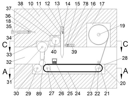
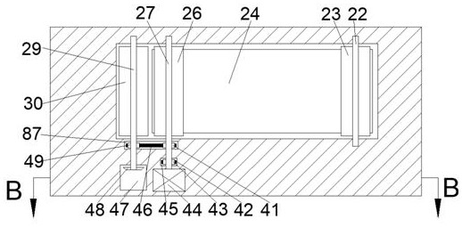
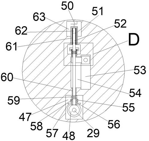
[0018] Combine below Figure 1-5 The present invention is described in detail, wherein, for the convenience of description, the orientations mentioned below are defined as follows: figure 1 The up, down, left, right, front and back directions of the projection relationship itself are the same.

[0019]A device suitable for coil forming of carbon fiber tubes with different diameters and different wall thicknesses described in conjunction with accompanying drawings 1-5 includes a main box body 10, and a feeding cavity 32 is provided through the left and right sides of the main box body 10. The upper side of the feeding chamber 32 is connected with a carbon fiber storage chamber 17, the lower side of the feeding chamber 32 is connected with a conveyor belt chamber 28, and the upper side of the feeding chamber 32 is connected with a tube core pressing wheel chamber 33. The feeding chamber 32 The upper side communicates with a cutting knife sliding chamber 12, the left side of the...


PUM


Abstract

The invention relates to the related field of new materials, and discloses a device suitable for coiling and forming carbon fiber pipes with different diameters and different wall thicknesses. The device comprises a main box body, wherein a feeding cavity is formed in the main box body in a left-right penetrating mode, the upper side of the feeding cavity communicates with a carbon fiber storage cavity, and the lower side of the feeding cavity communicates with a conveying belt cavity; the upper side of the feeding cavity communicates with a pipe core pressing wheel cavity, the upper side of the feeding cavity communicates with a cutting knife sliding cavity, and the left side of the cutting knife sliding cavity communicates with a half gear cavity. Carbon fibers are automatically cut offduring coiling and forming, the step of cutting the carbon fibers before pipe coiling is omitted, the pipe coiling efficiency is greatly improved, and meanwhile the carbon fiber cutting length can bechanged; and the pipe coiling thickness is variable, the applicability of the device is guaranteed, the device is suitable for the pipe coiling process of pipe cores with different diameters due to automatic clamping of a pipe core pressing wheel, meanwhile, the pipe cores are clamped in three directions through a rotating wheel, the pipe core pressing wheel and a left conveying wheel, carbon fiber pipe coiling and forming are more compact, and the forming quality of the carbon fiber pipes is greatly improved.

Description

technical field [0001] The invention relates to the related field of new materials, in particular to a device suitable for forming carbon fiber tubes with different diameters and different wall thicknesses. Background technique [0002] Carbon fiber data is one of today's new materials, which refers to high-strength and high-modulus fibers with a carbon content of more than 90% in the friction wheel cavity. Extruded (wrapped), the current carbon fiber tube roll forming equipment needs to cut the carbon fiber into a specified length before operation, and then use two relatively moving plates to roll the carbon fiber onto the tube core, so that the roll tube The efficiency is not high. If you need to produce carbon fiber tubes with different wall thicknesses, you need to re-cut the carbon fiber length. Contents of the invention [0003] The object of the present invention is to provide a device suitable for forming carbon fiber tubes with different diameters and different w...

Claims


Application Information

Patent Timeline
Patent Type & Authority Applications(China)
IPC IPC(8): B29C70/32B29C70/34B29C70/38B29C70/54B29L23/00
CPCB29C70/32B29C70/34B29C70/38B29C70/541B29C70/543B29C70/545B29L2023/22
Inventor 黄文绩
Owner TAIZHOU LUQIAO NANRUI INTELLIGENT EQUIP TECH CO LTD
Learn More