Real-time signal strength display of terrestrial digital television signals

a digital television and real-time signal technology, applied in the field of digital television signals, can solve the problem that the signal strength of some digital signals (channels) may be too low to tune (or receive)

Inactive Publication Date: 2006-01-10
INTERDIGITAL CE PATENT HLDG
View PDF16 Cites 69 Cited by
  • Summary
  • Abstract
  • Description
  • Claims
  • Application Information

AI Technical Summary

Benefits of technology

[0012]In accordance with an aspect of the present invention, the user has the ability to scroll through a list of channels that are currently in the channel list. When any specific channel is selected, the tuner will play audio and video for that channel, as the real-time signal strength is updated on-screen (digital channels only). The list of channels that are currently available includes both analog and digital channels in order to provide the user with an integrated channel screen where the effects of an antenna adjustment on both digital and analog channels may be easily seen.

Problems solved by technology

If the user were to adjust or relocate the antenna, the signal strength of some digital signals (channels) may be too low to tune (or receive).

Method used


Image

  • Real-time signal strength display of terrestrial digital television signals
  • Real-time signal strength display of terrestrial digital television signals
  • Real-time signal strength display of terrestrial digital television signals

Examples


Embodiment Construction

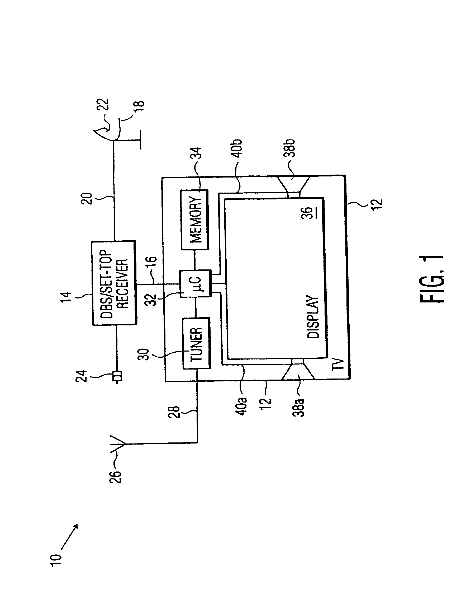
[0021]Referring to FIG. 1, there is shown a simplified, functional block diagram of a multimedia system 10. Multimedia system 10 may include TV or monitor 12 and DBS and / or set-top box receiver 14, which is in communication with TV 12 via communication line 16 as is known in the art. DBS (Direct Broadcast Satellite) receiver 14 is in communication with dish (or antenna) 18 via communication line 20 as is known in the art. Dish 18 receives digital multimedia and / or data signals, e.g. television, music and / or internet signals (hereinafter collectively “television signals”), that are focused onto and received by feedhorn / LNA (Low Noise Amplifier) unit 22. Feedhorn / LNA unit 22 typically receives and slightly amplifies the received television signals and transmits the amplified television signals to DBS receiver 14 for processing. DBS unit 14 may also be coupled to a CATV or cable system (not shown) via cable input line 24. TV 12 may be coupled to antenna or aerial 26 via communication l...


PUM


Abstract

An HDTV receiver coupled to a terrestrial antenna displays real-time signal strength of terrestrial digital television signals. A graphical user interface preferably displays various data relating to all terrestrial television signals in a scrollable grid format. The grid is displayed within an active video display of a selected television signal from the grid. Audio for the selected channel is also active.

Description

CROSS-REFERENCE TO RELATED APPLICATIONS[0001]This is a non-provisional patent application based on co-pending provisional patent application Ser. No. 60 / 139,467 filed Jun. 16, 1999, and co-pending provisional patent application Ser. No. 60 / 143,341, filed Jul. 12, 1999, which is hereby incorporated herein by reference, and which claims the benefit under 35 U.S.C. § 365 of International Application PCT / US00 / 15760, filed Jun. 8, 2000, which was published in accordance with PCT Article 21(2) on Dec. 21, 2000 in English.BACKGROUND OF THE INVENTION[0002]1. Field of the Invention[0003]The present invention relates to digital television signals and, more particularly, to the receipt and measurement of off-air digital television signals.[0004]2. Description of the Related Art[0005]High Definition television (HDTV) sets and other digital digital set-top boxes must be able to receive digital signals, for example, terrestrial television signals. Terrestrial digital television signals will be re...

Claims


Application Information

Patent Timeline
Patent Type & Authority Patents(United States)
IPC IPC(8): H04N5/50
CPCH04N5/50H04N21/4345H04N21/488H04N21/4383H04N21/44209H04N21/4314H04N21/485
Inventor KLOPFENSTEIN, SCOTT EDWARDDINWIDDIE, AARON HALSCHNEIDEWEND, DANIEL RICHARD
Owner INTERDIGITAL CE PATENT HLDG
Why Eureka
Try Eureka