Electrical connector between two end points

a technology of electrical connectors and end points, applied in the direction of current collectors, electrical apparatus, rotary current collectors, etc., can solve the problems of faulty transmission, wear of sliding contacts or slip rings conventionally used, transmission signals between stationary parts and the rotatable steering wheel of the motor vehicle, etc., and achieve the effect of simplifying the connection of continuing connecting lines

Inactive Publication Date: 2006-02-07
NEXANS
View PDF18 Cites 4 Cited by
  • Summary
  • Abstract
  • Description
  • Claims
  • Application Information

AI Technical Summary

Benefits of technology

[0005]The object of the present invention is to design the aforementioned connector in such a way that the connection of continuing connecting lines can be simplified.

Problems solved by technology

A significant problem associated with this use is the transmission of signals between stationary parts and the rotatable steering wheel of the motor vehicle.
The sliding contacts or slip rings conventionally used are subject to wear, and in particular at low current intensity are hardly usable due to fluctuating contact resistances, which can result in faulty transmission.
Depending on the chosen connection method, both ends of the connector must be equipped, which is costly.

Method used


Image

  • Electrical connector between two end points
  • Electrical connector between two end points
  • Electrical connector between two end points

Examples


Embodiment Construction

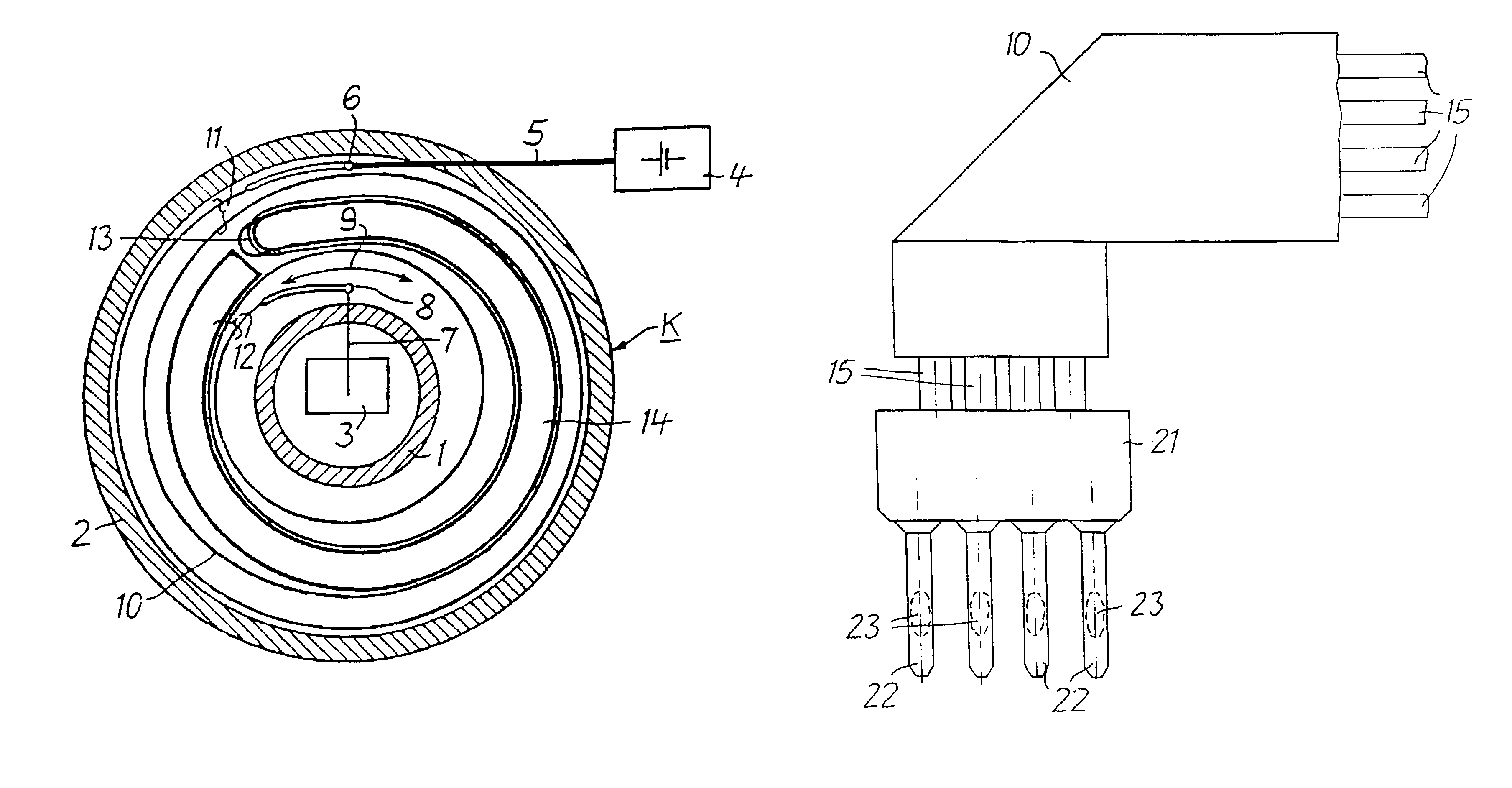
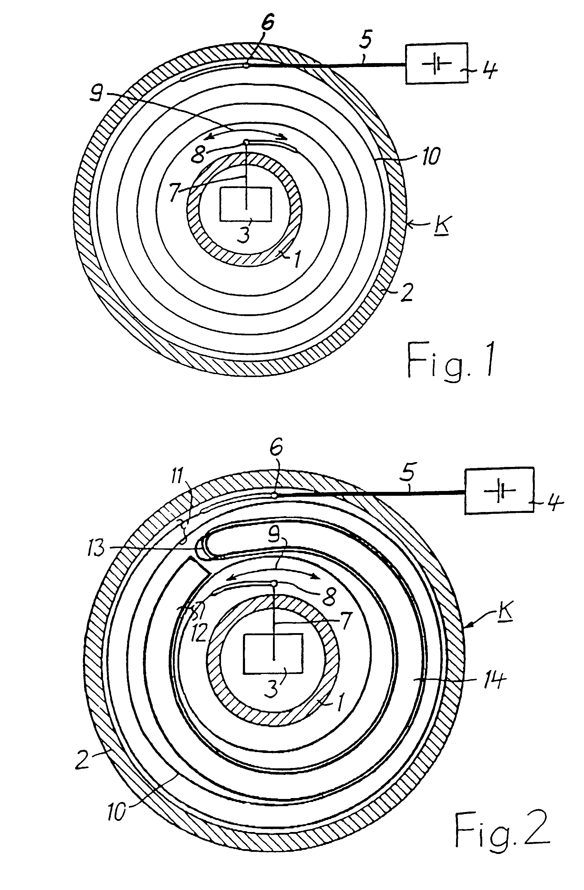
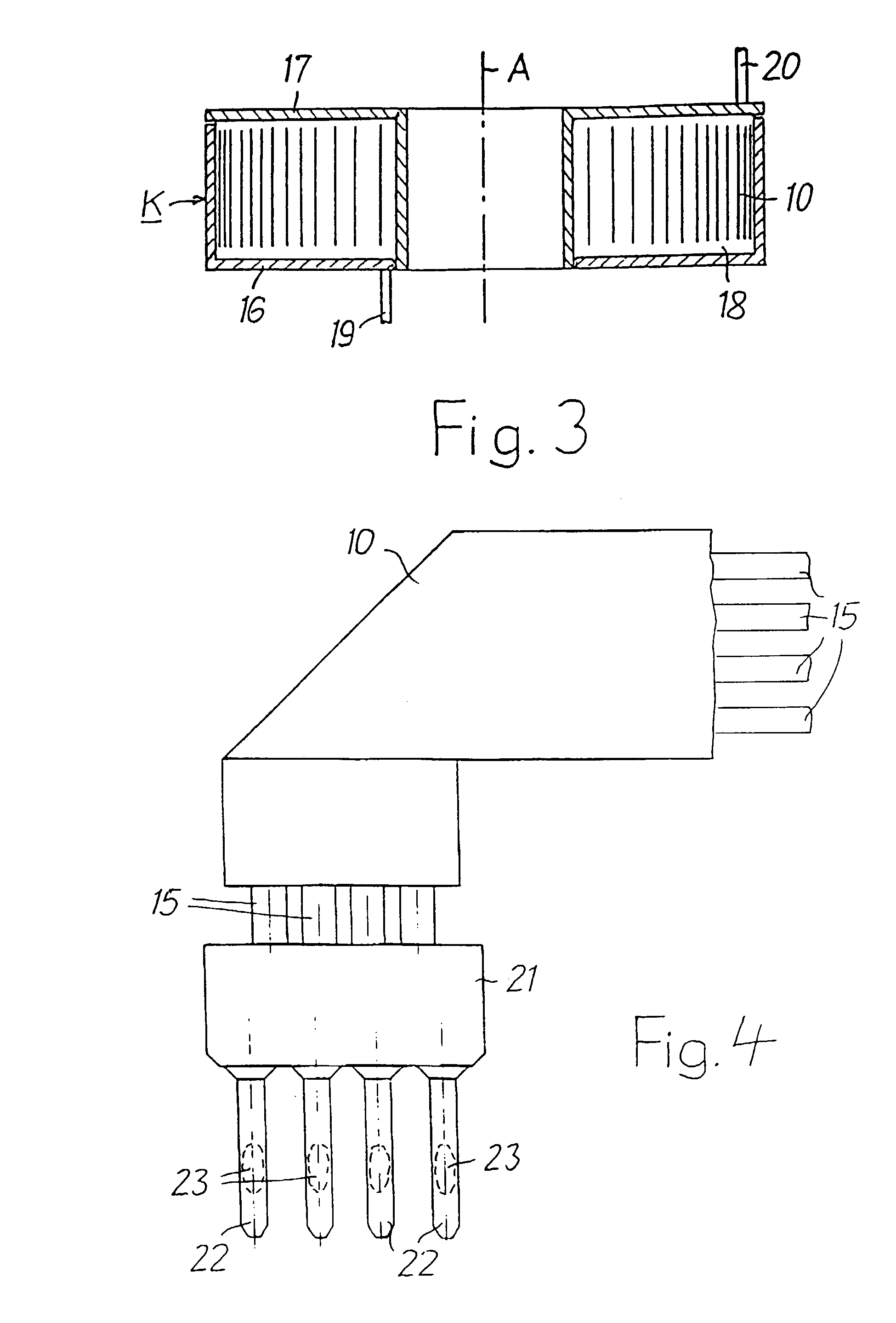
[0013]FIGS. 1 and 3 schematically show two walls 1 and 2 having a circular design, for example, of a cassette K comprising a stator 16 and a rotor 17 which is rotatable relative to the stator about a common axis A. The cassette is intended for installation in the steering wheel of a motor vehicle. To supply power to an electronic unit 3 by the signal of which an airbag can be deployed, cassette K is connected to a battery 4 in the motor vehicle. Battery 4 is connected via an electrical connecting line 5 to an end point 6 which is situated on stator 16 of the cassette and designed as a stationary point. Electronic unit 3 is connected via an electrical connecting line 7 to an end point 8 of cassette K, the end point being movable along with rotor 17 of cassette K in the direction of double arrow 9. In principle, end point 8 could be stationary and end point 6 could be movable, with a correspondingly different arrangement with respect to stator 16 and rotor 17 of cassette K.

[0014]An el...


PUM


Abstract

An electrical connector between relatively movable end points, comprises a cassette having a stator which is stationary in the mounted position and a rotor which is rotatable relative to the stator about a common axis, the stator and rotor each bearing one of the end points. In the cassette, between the stator and the rotor, an electrical conductor (10) running in a coiled fashion is situated with its ends fixed to the end points in order to connect to continuing connecting lines. To simplify connection of the connecting lines, an identical electrical contact element is attached to each end of the conductor (10). The electrical contact element is provided with pins (22) which are suitable as contact pins for attaching a plug and as contact surfaces for fixedly connecting the conductors of a connection line.

Description

[0001]This application is based on and claims the benefit of German Patent Application No. 10162127.2 filed Dec. 18, 2001, which is incorporated by reference herein.BACKGROUND OF THE INVENTION[0002]The invention relates to an electrical connector between two end points, one of which is movable relative to the other, comprising a cassette having a stator which is stationary in the mounted position and a rotor which is rotatable relative to the stator about a common axis, the stator and rotor each bearing one of the end points. In the cassette, between the stator and the rotor, an electrical conductor running in a coiled fashion is situated with its ends fixed to the end points in order to connect to continuing connecting lines. (European Patent 0 417 350 B1).[0003]Such a connector is used, for example, for transmitting signals to deploy airbags provided in motor vehicles for collision protection, or for transmitting signals to other components in motor vehicles. For the transmission ...

Claims


Application Information

Patent Timeline
Patent Type & Authority Patents(United States)
IPC IPC(8): H01R39/00H01R35/02
CPCH01R35/025
Inventor HUSCHER, RAINERREBHAN, HELMUT
Owner NEXANS
Why Eureka
Try Eureka