Real-time optical correlating system

Inactive Publication Date: 2006-02-14
UNITED STATES OF AMERICA THE AS REPRESENTED BY THE SEC OF THE ARMY
View PDF3 Cites 3 Cited by
  • Summary
  • Abstract
  • Description
  • Claims
  • Application Information

AI Technical Summary

Problems solved by technology

In optical correlation applications, the holographic filter must be captured optically on film or computed digitally and displayed on high-resolution devices, just as in the traditional process alluded to above with all the attendant time and processing limitations.

Method used


Image

  • Real-time optical correlating system
  • Real-time optical correlating system
  • Real-time optical correlating system

Examples


Embodiment Construction

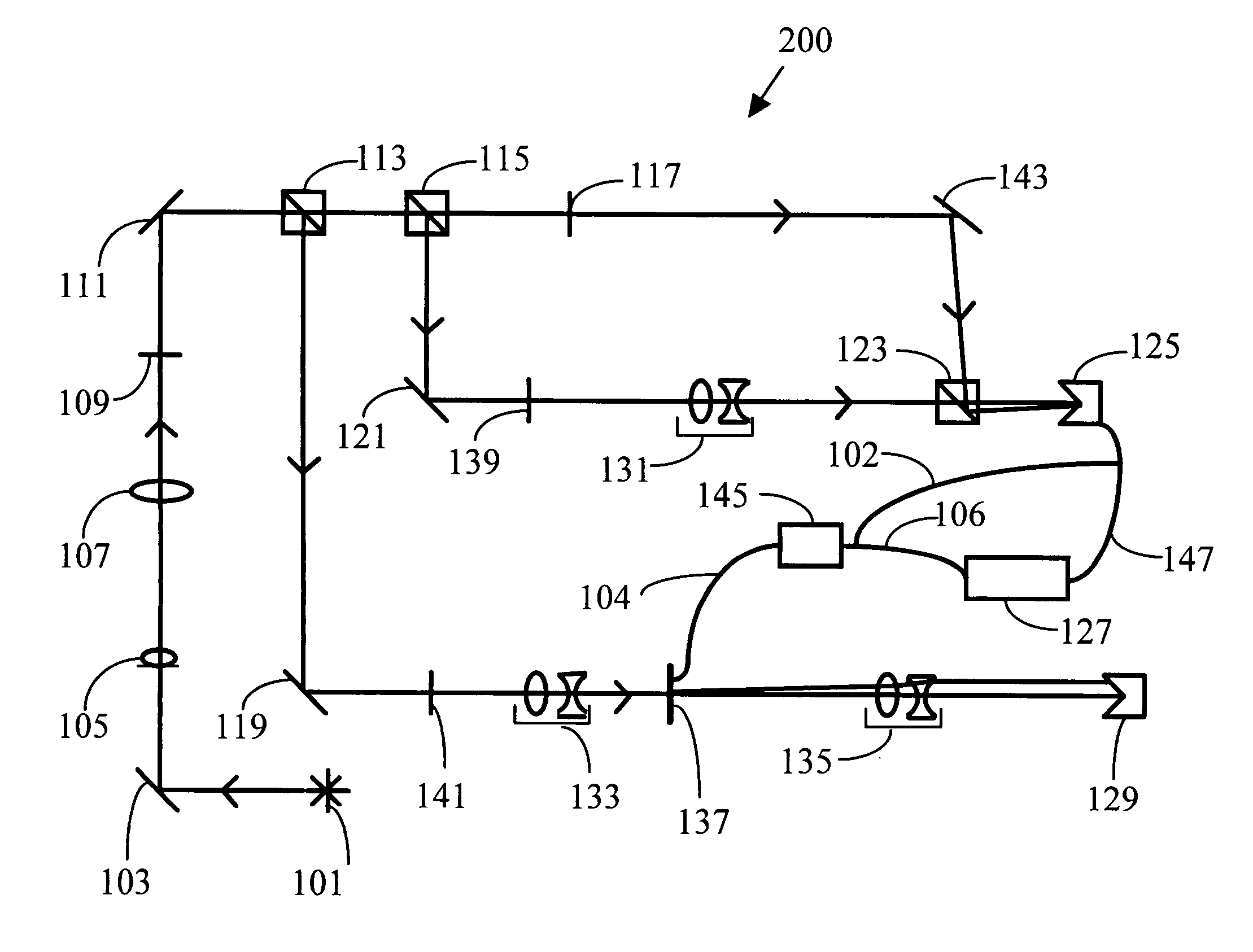
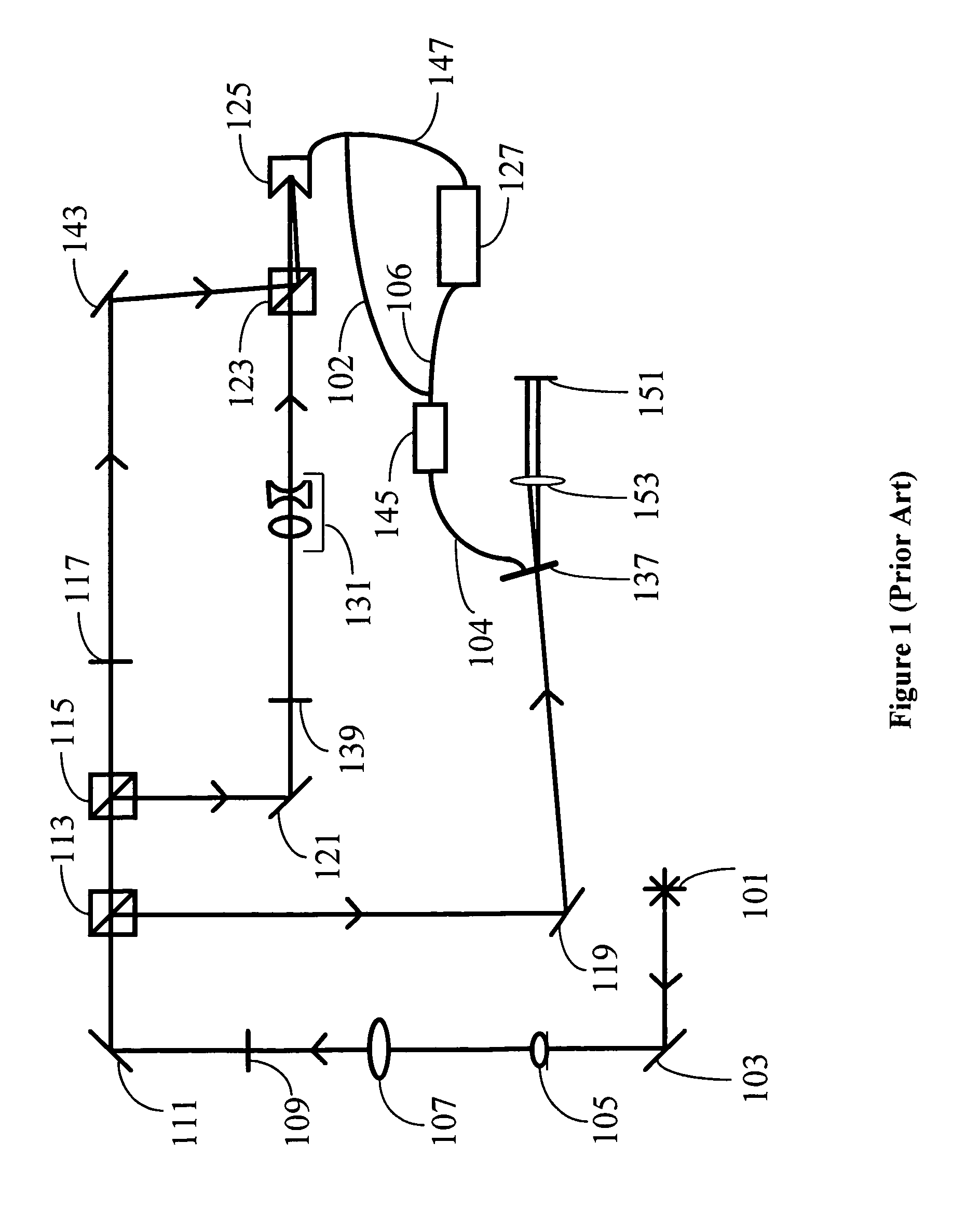
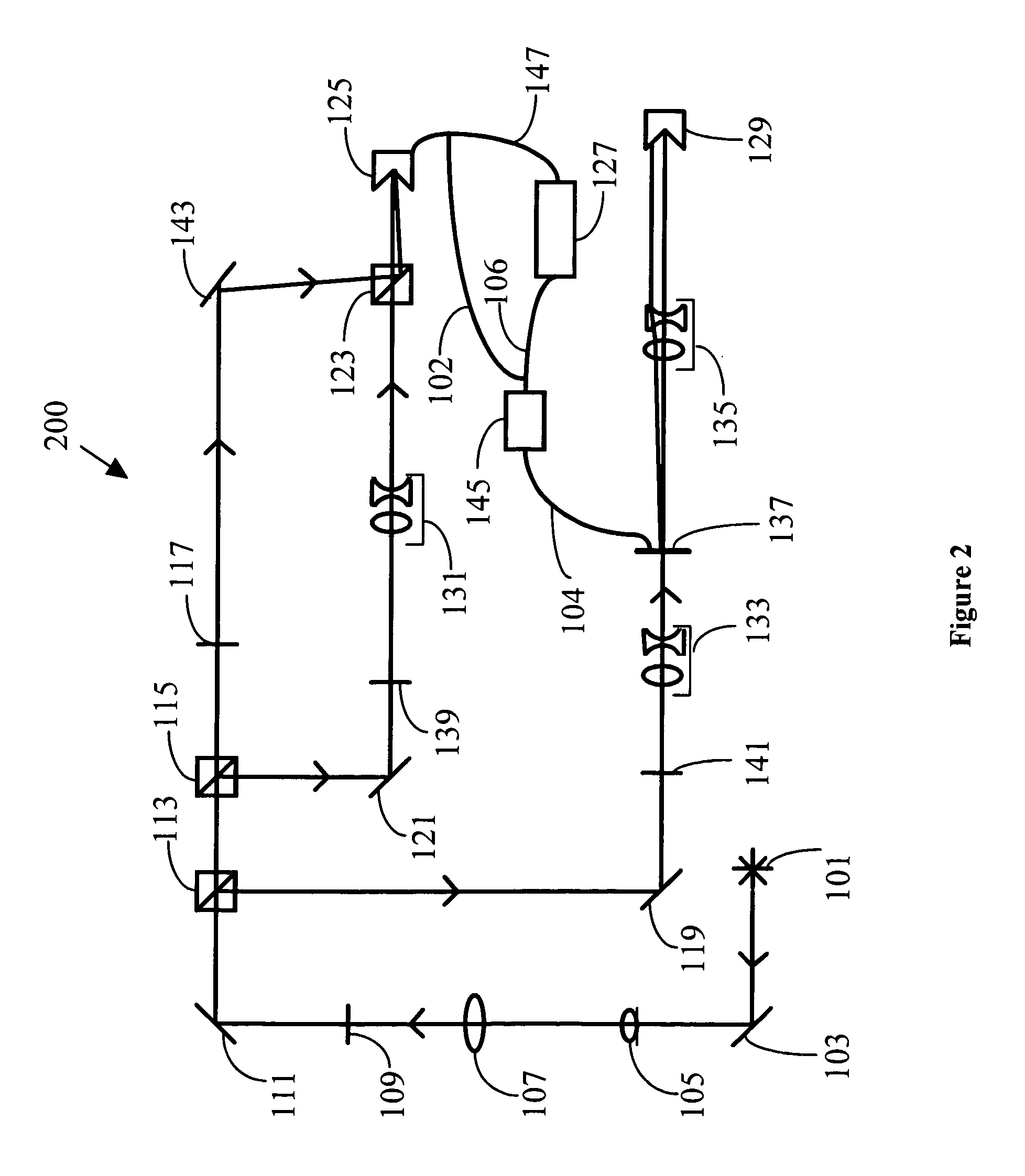
[0007]Referring now to the drawing wherein like numbers represent like parts in each of the figures and arrows indicate optical paths, FIG. 1 shows the part of the Real-Time Optical Correlating System that produces and reconstructs a hologram of input scene 139. Since FIG. 2 subsumes FIG. 1 as a necessary part of the entire Real-Time Optical Correlating System, subsequent explanation of the operation of the System is given with reference mostly to FIG. 2.

[0008]I. Recordation and Reconstruction of a Hologram of Input Scene 139.

[0009]Initially, a suitable laser source 101, such as a 15-milliwatt neodymium-doped yttrium vanadate laser (Nd:YVO4), emits an original laser beam of an appropriate wavelength, such as 532 nanometers. It is directed by first mirror 103 to impinge on spatial filter 105 whereby it is cleaned and rendered to be more Gaussian in nature. Thence, the original beam travels through collimating lens 107 which may be any positive lens and through linear polarizer 109 wh...


PUM


Abstract

A Real-Time Optical Correlating System produces holograms that contain both amplitude and phase information and have none of the time constraints of the traditional holographic methods. It has been demonstrated to operate at television field rates (60 Hz) employing currently available devices of moderate resolution. Using the System, the holographic matched filter of an input scene is calculated optically as an analog sum, captured by a charge-coupled device (CCD) camera and transmitted directly or through a computer to and displayed on a commercially available liquid crystal display (LCD) device. The correlation plane may be viewed immediately on a suitable screen because there is no film to process or computer calculations to be performed. Concurrently with the creation of the holographic matched filter of the input scene, a Fourier transform of a test scene is produced and both are imaged on another charge-coupled device camera for any correlation between the input and test scenes.

Description

DEDICATORY CLAUSE[0001]The invention described herein may be manufactured, used and licensed by or for the Government for governmental purposes without the payment to us of any royalties thereon.BACKGROUND OF THE INVENTION[0002]In traditional holography and holographic image processing, the interference pattern is recorded on high-resolution film. More recently, digital computation of holograms has become possible if information about the object and the desired reconstruction angle is known. With either of these methods, however, reconstructing a viewable image from a stored hologram requires that either the film be developed, which can take an hour or more to process and dry or that the digitally computed hologram be displayed on a high-resolution electrically addressable display device which can require on the order of several minutes to compute the hologram from a collection of digitized two dimensional images. (A third technique, which is not truly holographic, employs several p...

Claims


Application Information

Patent Timeline
Patent Type & Authority Patents(United States)
IPC IPC(8): G01B9/02
CPCG03H1/04G03H1/2294G06K9/745G03H2226/11G03H2001/0445G06V10/895
Inventor KRANSTEUBER, AMY SUEGREGORY, DON A.
Owner UNITED STATES OF AMERICA THE AS REPRESENTED BY THE SEC OF THE ARMY
Why Eureka
Try Eureka