Color image forming apparatus with a removable and inclined intermediate transfer body unit

Inactive Publication Date: 2006-04-18
PANASONIC CORP
View PDF14 Cites 16 Cited by
  • Summary
  • Abstract
  • Description
  • Claims
  • Application Information

AI Technical Summary

Benefits of technology

[0016]Accordingly, an object of the present invention is to provide a color image forming apparatus which is reduced in size, ensures the stable picture quality regardless of the thickness and a moisture absorbing property of the sheet and others, makes it easy for the user to remove a jammed sheet at the time of paper jamming, and provides an easy work of replacing the image forming units as expendables.
[0017]The present invention may be described in at least the following conceptual descriptions: (1) A plurality of image forming units are individually positioned to and held with an intermediate transfer body unit; (2) A plurality of photo-receptors are fixedly supported by one housing to form an assembled photo-receptor unit, the assembled photo-receptor unit being positioned to and held with the intermediate transfer body unit; and (3) One of plural photo-receptors is fixed to and supported by one housing to form a photo-receptor unit, and the remaining photo-receptors are fixed to and supported by one housing to form an assembled photo-receptor unit, and the photo-receptor unit and the assembled photo-receptor unit are individually positioned to and held with the intermediate transfer body unit. An intermediate transfer body unit and a plurality of image forming units are integrally assembled. With this feature, in attaching the image forming units to the apparatus main body, sufficient strength of the image forming units is secured while the size of the whole image forming apparatus is reduced. The stable picture quality is ensured regardless of the thickness and a moisture absorbing property of the sheet and others. Further, the user can remove a jammed sheet at the time of paper jamming.
[0018]Further, the image forming units have sizes suitable for expendables. A sufficient working space is secured. Operability in the replacing work of the image forming units is enhanced.
[0019]Further, the present invention may be described such that image forming units are vertically arranged from upstream to downstream sides as viewed in a color forming process flow, while being successively shifted to optical units which are respectively arranged adjacent to the image forming units and at the same heights as of the image forming units. This feature advantageously brings about reduction of an installation area and a height of a main body of the color image forming apparatus, and a size of the whole image forming apparatus.

Problems solved by technology

This results in insufficient stability of the image reproduction.
As a result, the recording sheet tends to slip at the attracting part, possibly causing the out-of-color-registration
In the event of jamming such as paper jamming during a continuous printing operation, in particular in the event that the recording medium is left at a portion where the images are successively transferred on the recording medium, it is difficult to remove the jammed sheet.
Accordingly, there is much chance that his / her hands and clothes are frequently soiled, and further the color toner particles fly into the air to contaminate air.
This results in insufficient rigidity of the image forming units per se and the drive means.
Where the insufficient rigidity is present, it is difficult to secure the positioning accuracy of the image forming units and the drive accuracy as major factors in the image formation.
Accordingly, a space used by the user for replacement of the image forming units as expendables is narrow, and the operability is deteriorated in the replacement work.

Method used


Image

  • Color image forming apparatus with a removable and inclined intermediate transfer body unit
  • Color image forming apparatus with a removable and inclined intermediate transfer body unit
  • Color image forming apparatus with a removable and inclined intermediate transfer body unit

Examples


first embodiment

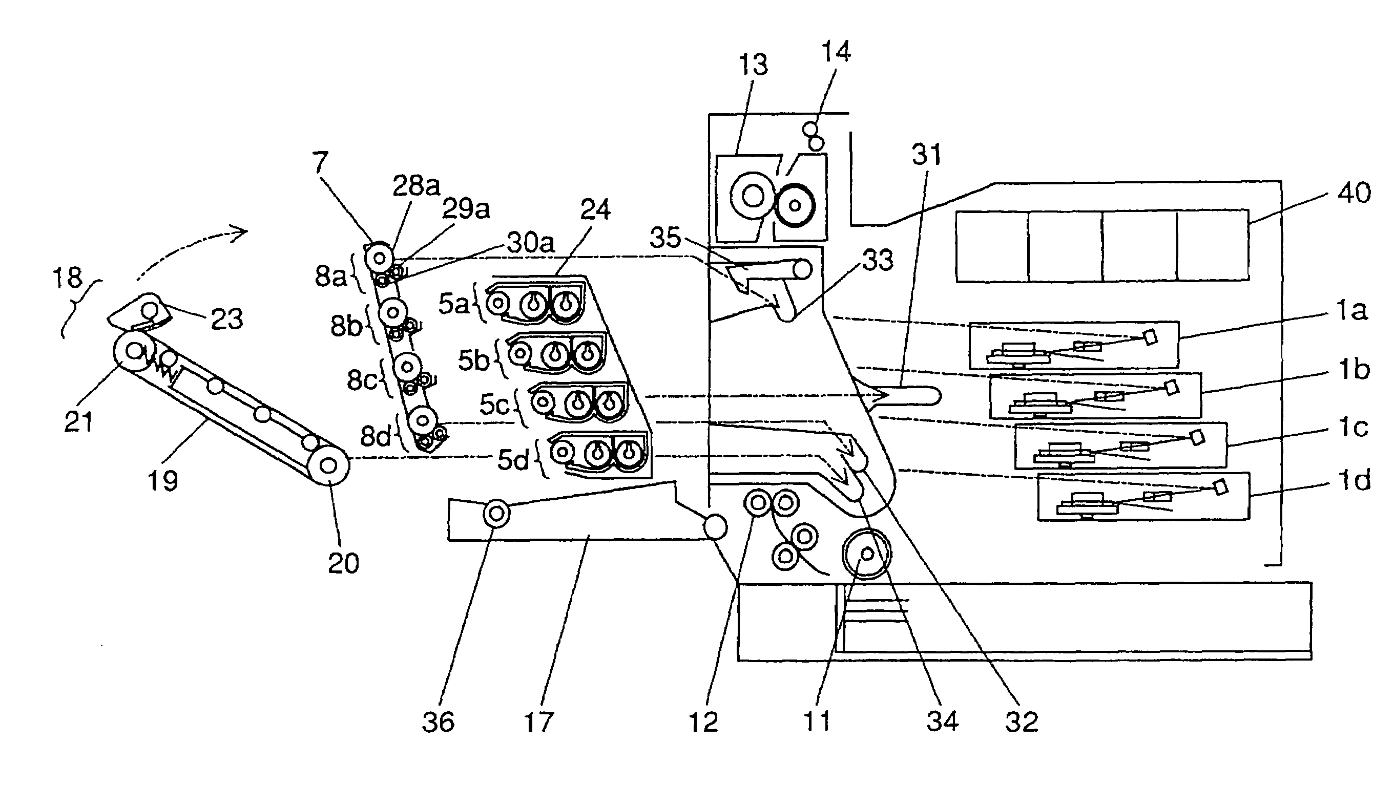
[0040]FIG. 3 is a view schematically showing how to attach the image forming units as expendables to and detaching them from the image forming apparatus. FIG. 4 is a view schematically showing the attaching of the image forming units in the

[0041]As shown in FIG. 3, a door 17 is attached to the left side of the apparatus main body. When the door 17 is opened, a component attaching opening is formed in the apparatus main body. The assembled developing unit 24 and the integral cartridge of the photo-receptor units 8 (8a to 8d) and the intermediate transfer body unit 18 are is inserted into and taken out of the apparatus main body.

[0042]A transfer roller 36 is mounted on the door 17. When the door 17 is closed, the transfer roller 36 collectively transfers the toner images from the intermediate transfer belt 19 onto a recording sheet at a position where it is confronted with the upper belt follower roller 21 which tensionally supports the intermediate transfer belt 19.

[0043]In the insta...

fourth embodiment

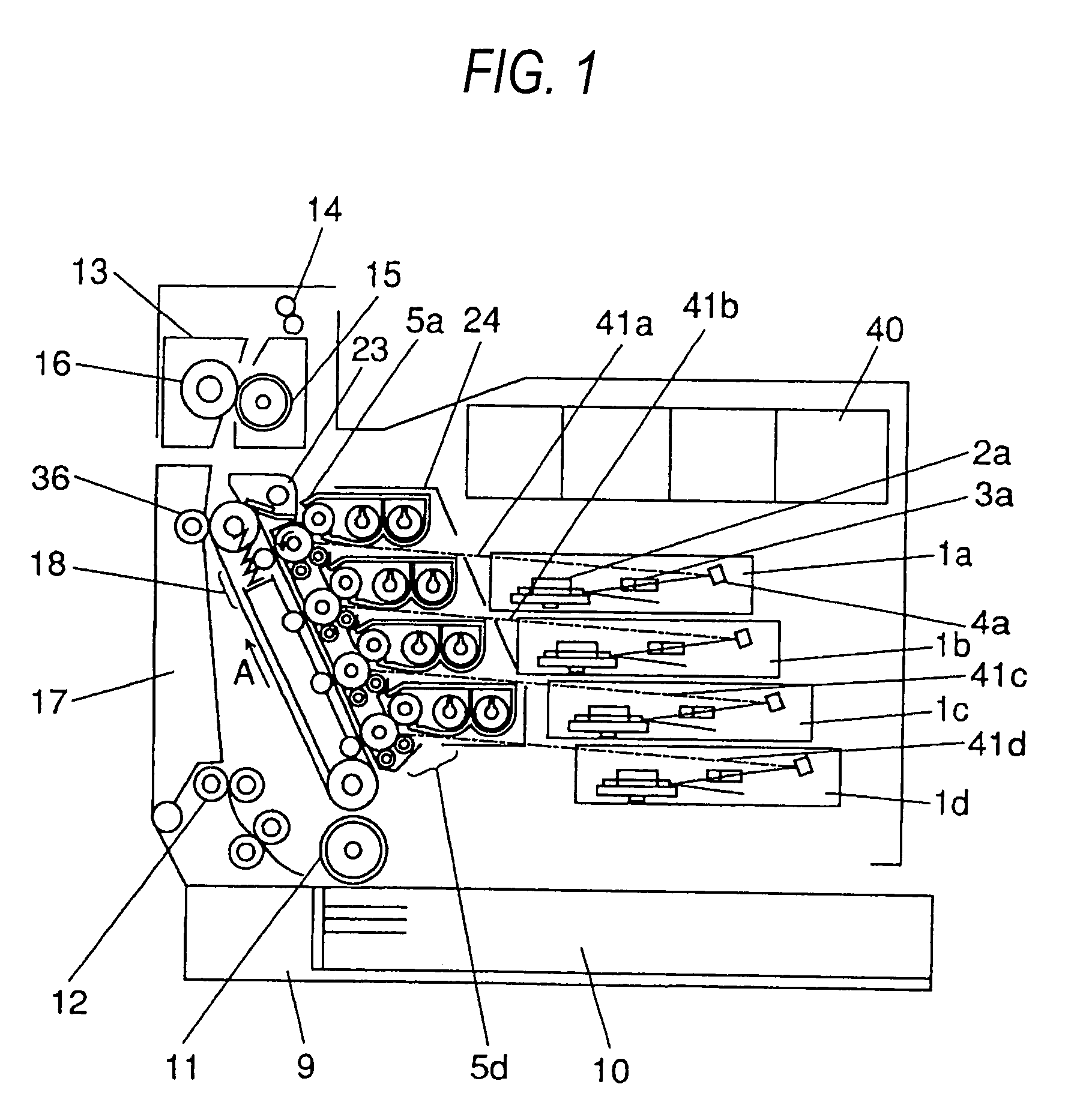
[0058]FIG. 7 is a view showing an image forming apparatus according to the invention. A housing of the main body is constructed as shown in FIG. 7, a door 17 is attached to the left side of the apparatus main body. When the door 17 is opened, a component attaching opening is formed in the apparatus main body. The assembled developing unit 24, the assembled photo-receptor unit 7 and the intermediate transfer body unit 18 are inserted into and taken out of the apparatus main body. A transfer roller 36 is mounted on the door 17. When the door 17 is closed, the transfer roller 36 collectively transfers the toner images from the intermediate transfer belt 19 onto a recording sheet at a position where it is confronted with the upper belt follower roller 21 which tensionally supports the intermediate transfer belt 19.

[0059]In the instant embodiment, as shown in FIG. 1, the sheet supply cassette 9 includes a feed roll 11 for feeding recording sheets 10 at predetermined timings. A registrati...


PUM


Abstract

A color image forming apparatus having a plurality of developing units for containing different color toners to form a color image, a plurality of photo-receptor units including photo-receptors on which electrostatic latent images to be developed by said developing units are to be formed, and an intermediate transfer body unit including a tensionally provided belt with upper and lower surfaces to which toner images are transferred from said photo-receptors, an intermediate transfer body unit cartridge integrally holding said intermediate transfer body unit, the cartridge being detachably attached to the color image forming apparatus through the jamming-removal opening.

Description

CROSS REFERENCE TO RELATED APPLICATION[0001]This application is based upon and claims the benefit of priority of Japanese Patent Application No. 2002-310748 filed on Oct. 25, 2002, and Japanese Patent Application No. 2002-325180 filed on Nov. 8, 2002, the contents of which are incorporated herein by reference in its entirety.BACKGROUND OF THE INVENTION[0002]The present invention relates to a color image forming apparatus, and more particularly to a color image forming apparatus of the type in which images formed by a plurality of image forming units are superimposed on an intermediate transfer belt, and those superimposed images are collectively transferred onto a recording sheet.[0003]In a conventional color Xerography basis image forming apparatus, a called tandem type image forming apparatus is employed for the purpose of increasing printing speed. In this type of the apparatus, image forming sections or units are arranged side by side. Toner images are successively superimposed ...

Claims


Application Information

Patent Timeline
IPC IPC(8): G03G21/18G03G15/08G03G21/16
CPCG03G21/16G03G2221/1675G03G2215/00544G03G21/1638
Inventor TANIZAKI, JUNICHITAJIMA, NORIYUKIKITAOKA, YOSHITAKATAMAI, YASUTAKA
Owner PANASONIC CORP
Why Eureka
Try Eureka