PWM switching direct voltage circuit

Inactive Publication Date: 2009-04-16
YU SHOU TE +1
View PDF1 Cites 4 Cited by
  • Summary
  • Abstract
  • Description
  • Claims
  • Application Information

AI Technical Summary

Benefits of technology

[0007]The main objective of the present invention is to have the corresponding values of the voltage-cycle of the PWM circuit in linear proportion when the PWM circuit is in operation to enhance the work efficiency of the PWM circuit, wherein it is achieved by having the rated value of the fourth passive device at least three times more than the rated value of the first passive device.

Problems solved by technology

However, in the most of PWM switching direct voltage circuit applied by power supply the corresponding values of

Method used


Image

  • PWM switching direct voltage circuit
  • PWM switching direct voltage circuit
  • PWM switching direct voltage circuit

Examples


Embodiment Construction

[0019]The other advantage, objective, technical feature and effectiveness of the present invention will be better understood by the detail description of preferred embodiment in conjunction with the following figure.

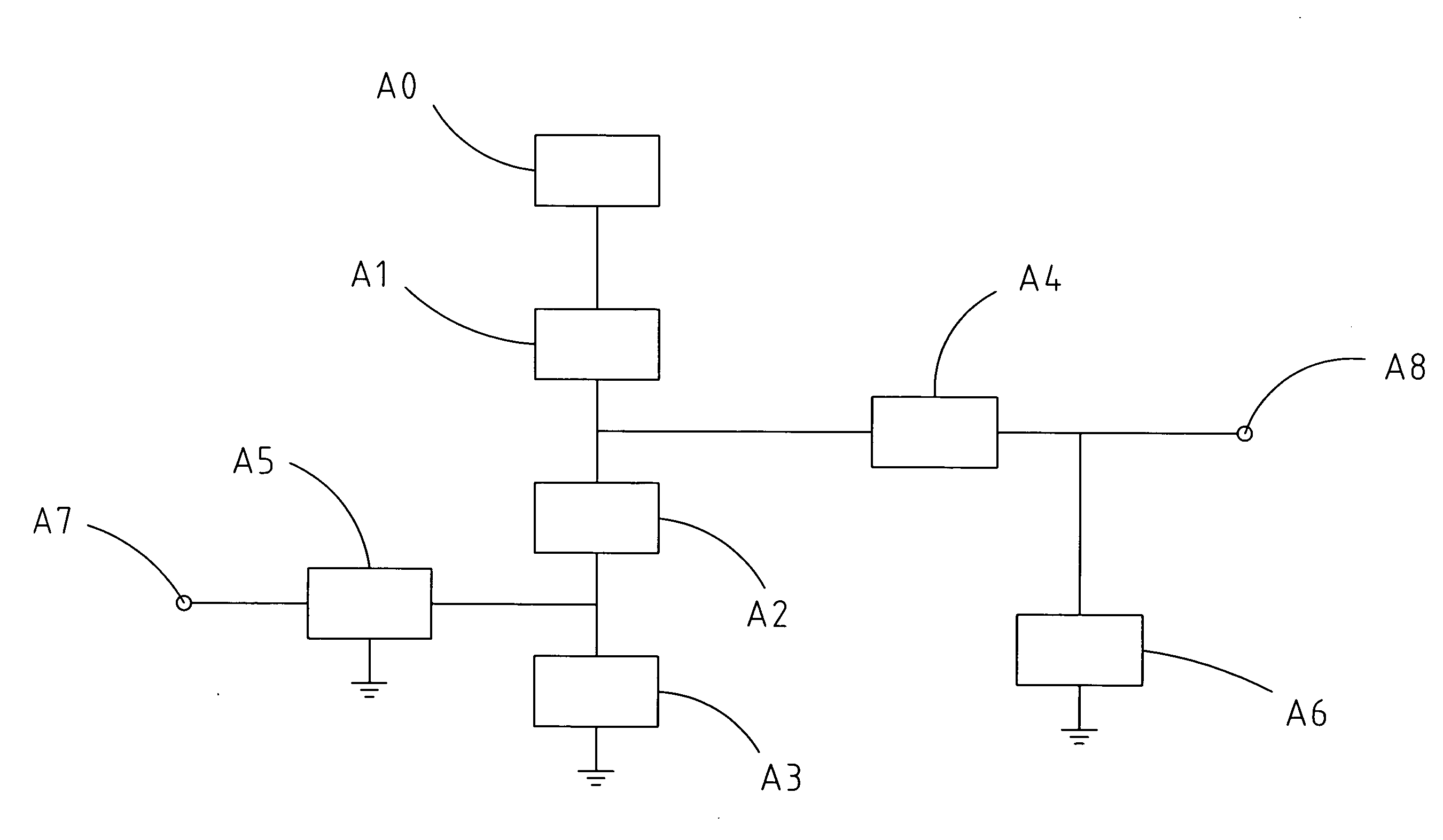
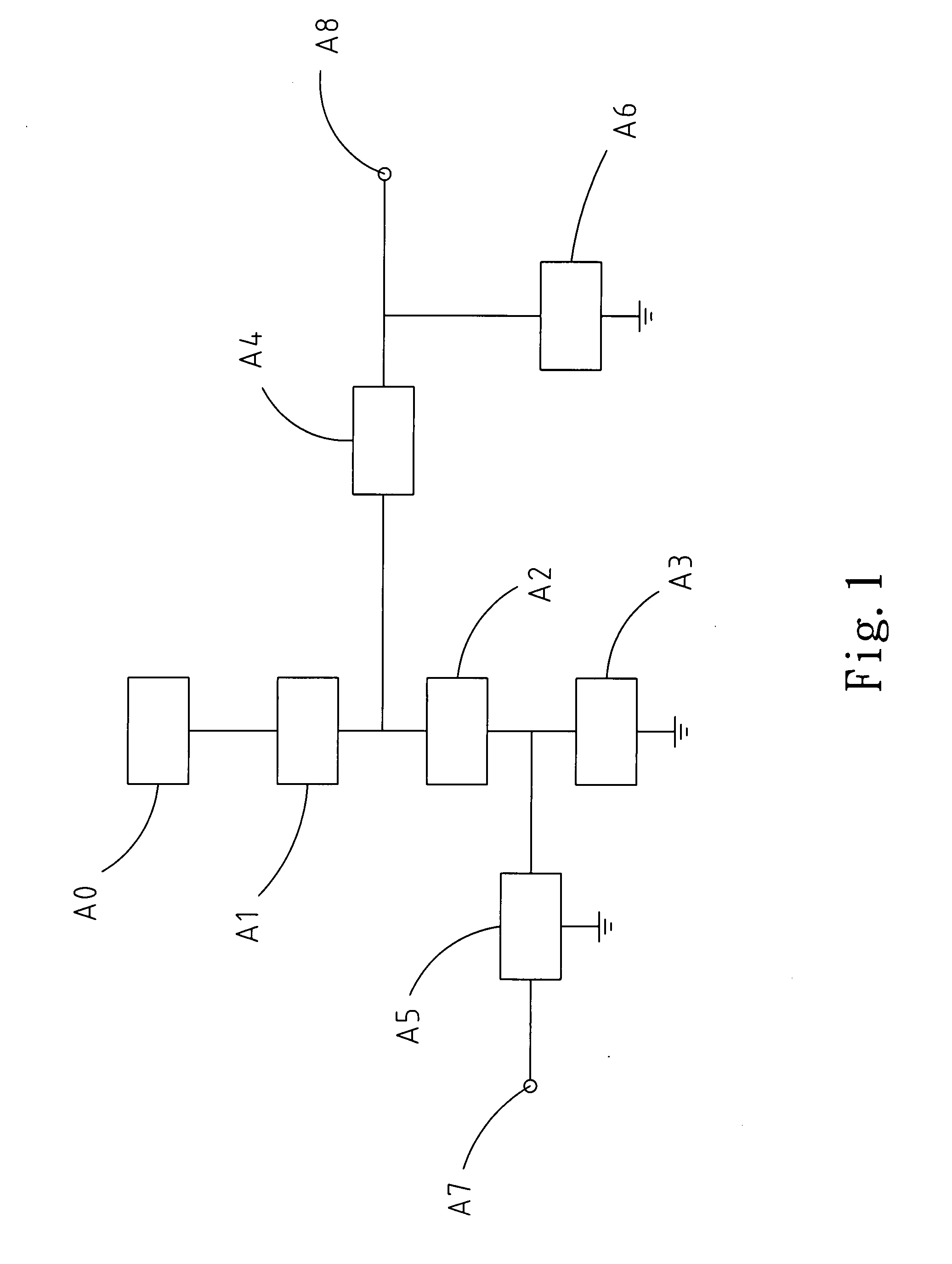
[0020]Referring to FIG. 1 and FIG. 2, the PWM circuit A of the present invention comprises a first passive device A1, a second passive device A2, a third passive device A3, a fourth passive device A4, an active device A5, an energy storage device A6, an input end A7 and an output end A8, wherein the power supply end A0 is connected with the first passive device A1, the second passive device A2 and the third passive device A3 orderly in series wherein the active device A5 is connected in parallel between the second passive device A2 and the third passive device A3, the fourth passive device A4 is connected in parallel between the first passive device A1 and the second passive device A2 and then connected in parallel with the energy storage device A6 and the output end A8,...


PUM


Abstract

The present invention relates to a pulse width modulation switching direct voltage circuit. The PWM circuit comprises a first passive device, a second passive device and a third passive device which they are connected orderly in series, and a fourth passive device which is connected in parallel between the first passive device and the second passive device, wherein the rated value of the fourth passive device is at least three times more than the rated value of the first passive device. Herewith, the voltage-cycle relationship of the PWM circuit becomes linear. Under such a state, the PWM circuit is enabled with good work efficiency.

Description

FIELD OF THE INVENTION[0001]The present invention relates to a PWM switching direct voltage circuit, particular to a PWM switching direct voltage circuit which the corresponding values of the duty cycle and the output voltage are adjusted to linear.BACKGROUND OF THE INVENTION[0002]Pulse width modulation (PWM) technology is a very effective technology by applying digital output of a microprocessor to control an analog circuit. It is widely applied in many fields such as measurement, communication, power control and transformation.[0003]In short, PWM is a method to encode an analog signal level digitally. By the application of a high resolution counter the duty cycle of a square wave is modulated to encode a specific analog signal level. PWM signal remains to be digital since at any specific moment the direct current supply with full value is either ON or OFF. The voltage or current supply is applied on an analog load by a repetitive pulse sequence of ON or OFF. The direct current sup...

Claims


Application Information

Patent Timeline
IPC IPC(8): H03K7/08
CPCH03K7/08H03K5/06
Inventor LI, CHING-SHENG
Owner YU SHOU TE
Why Eureka
Try Eureka