Back light unit

Active Publication Date: 2006-05-04
LG DISPLAY CO LTD
View PDF7 Cites 10 Cited by
  • Summary
  • Abstract
  • Description
  • Claims
  • Application Information

AI Technical Summary

Benefits of technology

[0036] An object of the present invention is to provide a back light unit for fixing lamps without soldering, thereby cutting expenses and enhancing work efficiency.

Problems solved by technology

A CRT is not capable of meeting the demands of miniaturization and lightweight due to its own weight and size.
However, the LCD apparatus employing the direct type back light may cause malfunction of lamps or introduce a short lamp life in the case that a large monitor and a large television employing the direct type back light is operated for a long period.
Also, in the case where a lamp does not operate in the edge type, only the brightness of the screen may deteriorate.
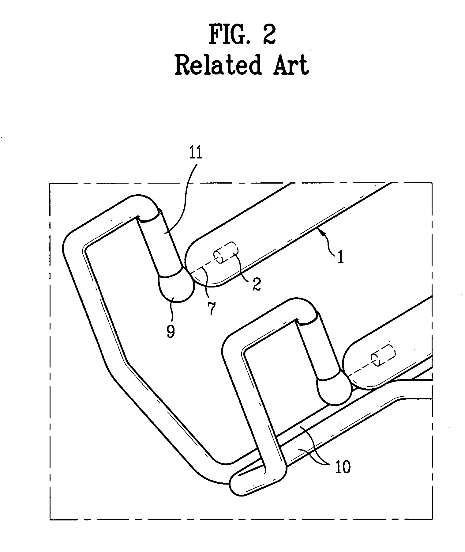
The disconnection of the inner lead line and the outer lead line may cause problems such as lighting malfunction, spark generation, and the like.
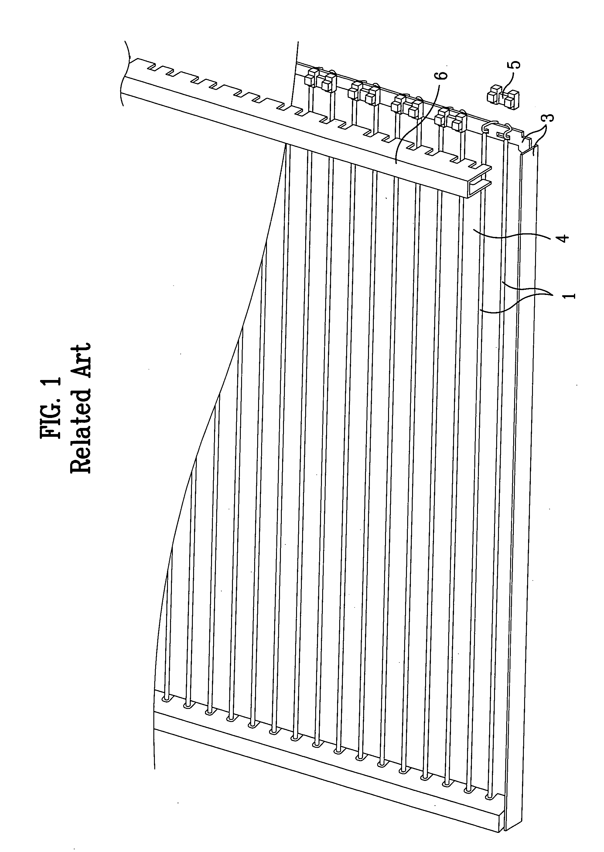
However, the conventional back light unit has the difficulty of preventing the soldered portion from falling apart, since the wires 39, 39a are fixed in the outer case 33 by soldering 40.

Method used


Image

  • Back light unit
  • Back light unit
  • Back light unit

Examples


first embodiment

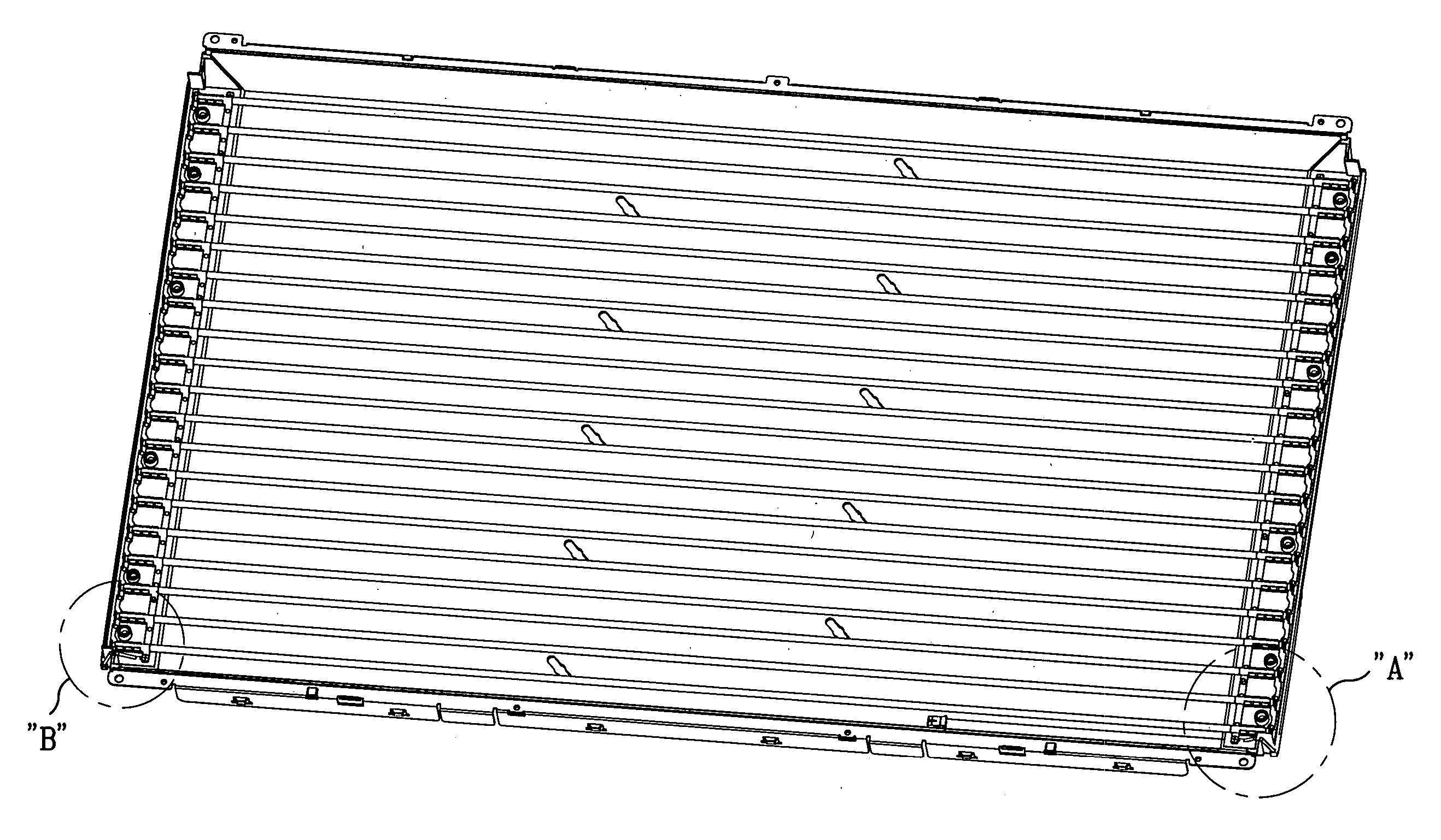
[0059] As shown in FIGS. 5 through 7, a back light unit according to the present invention utilizes a plurality of lamps 51, two common electrodes 53, first and second lower structures 54a and 54b, a plurality of screws 55, and two wires 56.

[0060] The plurality of lamps 51 is arranged at a predetermined distance, each lamp 51 having a lamp tube and two electrodes 50a, 50b on both outer ends of the lamp tube. The common electrodes 53 are formed in a gripper type to fix both ends of each lamp 51. The first and second lower structures 54a and 54b are formed below both ends of the lamps 51 in one direction to seat the common electrodes 53.

[0061] A plurality of fixing members, e.g., screws 55, clamps, etc., fix the common electrodes 53 to the first and second lower structures 54a and 54b, respectively. The wires 56 connect the common electrodes 53 with an inverter (not shown).

[0062] As shown in FIG. 7, each common electrode 53 comprises a plurality of fastening parts 58, first and seco...

second embodiment

[0074] Consequently, the back light unit of the present invention alternately disposes semicircular elastic members having different lengths at predetermined intervals, whereby the gripping members and the lamps are in effective contact, thereby enhancing the reliability of the goods.

[0075] As shown in FIG. 8, each common electrode 53 contains a plurality of fastening parts 58, each of the fastening parts 58 having a plurality of gripping members.

[0076] Each of the plurality of gripping members has a first semicircular elastic member 58a and a second semicircular elastic member 58b, the first semicircular elastic member 58a having different length from the second semicircular elastic member 58b. In the plurality of gripping members, a first gripping member has the first semicircular elastic member 58a having a length shorter than the second semicircular elastic member 58b, and a second gripping member has the first semicircular elastic member 58a having a length longer than the sec...


PUM


Abstract

A back light unit includes a plurality of lamps arranged at predetermined distances from each other, each lamp having a lamp tube provided with electrodes at both ends thereof. Common electrodes communicate with both ends of said plurality of lamps and contain a plurality of gripping members for accomodating each of said plurality of lamps. A plurality of releasable connectors fix the common electrodes to first and second lower structures formed below both ends of the plurality of lamps. Electrical connecting elements connect the common electrodes to an inverter.

Description

[0001] This application claims the benefit of the Patents Korean Application No. P2004-89250, filed on Nov. 4, 2004, which is hereby incorporated by reference as if fully set forth herein. BACKGROUND OF THE INVENTION [0002] 1. Field of the Invention [0003] The present invention relates to a back light unit, and more particularly, to a back light unit which has common electrodes capable of applying electrical power to light-emitting lamps without soldering. [0004] 2. Discussion of the Related Art [0005] Generally, a CRT (Cathode Ray Tube) is employed for a monitor of a TV, of a measuring instrument and of an information terminal. A CRT is not capable of meeting the demands of miniaturization and lightweight due to its own weight and size. [0006] A CRT is expected to be replaced by a LCD (Liquid Crystal Display), a PDP (Plasma Display Panel) and an ELD (Electro Luminescence Device) due to the limit of weight and size. The LCD uses the field optical effect, a PDP uses a discharging gas...

Claims


Application Information

Patent Timeline
IPC IPC(8): F21S4/00
CPCG02F1/133604G02F1/133608H01R33/0827
Inventor KIM, JAE BUMOH, SEOK HWANMOON, KWAN SIK
Owner LG DISPLAY CO LTD
Why Eureka
Try Eureka