
Double shielded electrical connector

a double shielded, electrical connector technology, applied in the direction of coupling devices, two-part coupling devices, electrical apparatus, etc., can solve the problems of electrical connectors being fragile and weaken the integrity of shrouds

Inactive Publication Date: 2006-05-02
HON HAI PRECISION IND CO LTD
View PDF10 Cites 12 Cited by
  • Summary
  • Abstract
  • Description
  • Claims
  • Application Information

AI Technical Summary

Benefits of technology

The design enhances the structural integrity and reliability of the electrical connector, preventing damage and ensuring secure latching without compromising the shroud's strength.

Problems solved by technology

Obviously, the latching hooks of the shroud result in two pairs of openings opened therein, which not only weaken the shroud integrity but further make the electrical connector fragile.

Method used


Image

  • Double shielded electrical connector
  • Double shielded electrical connector
  • Double shielded electrical connector

Examples


Embodiment Construction

[0014]Reference will now be made to the drawing figures to describe the present invention in detail.

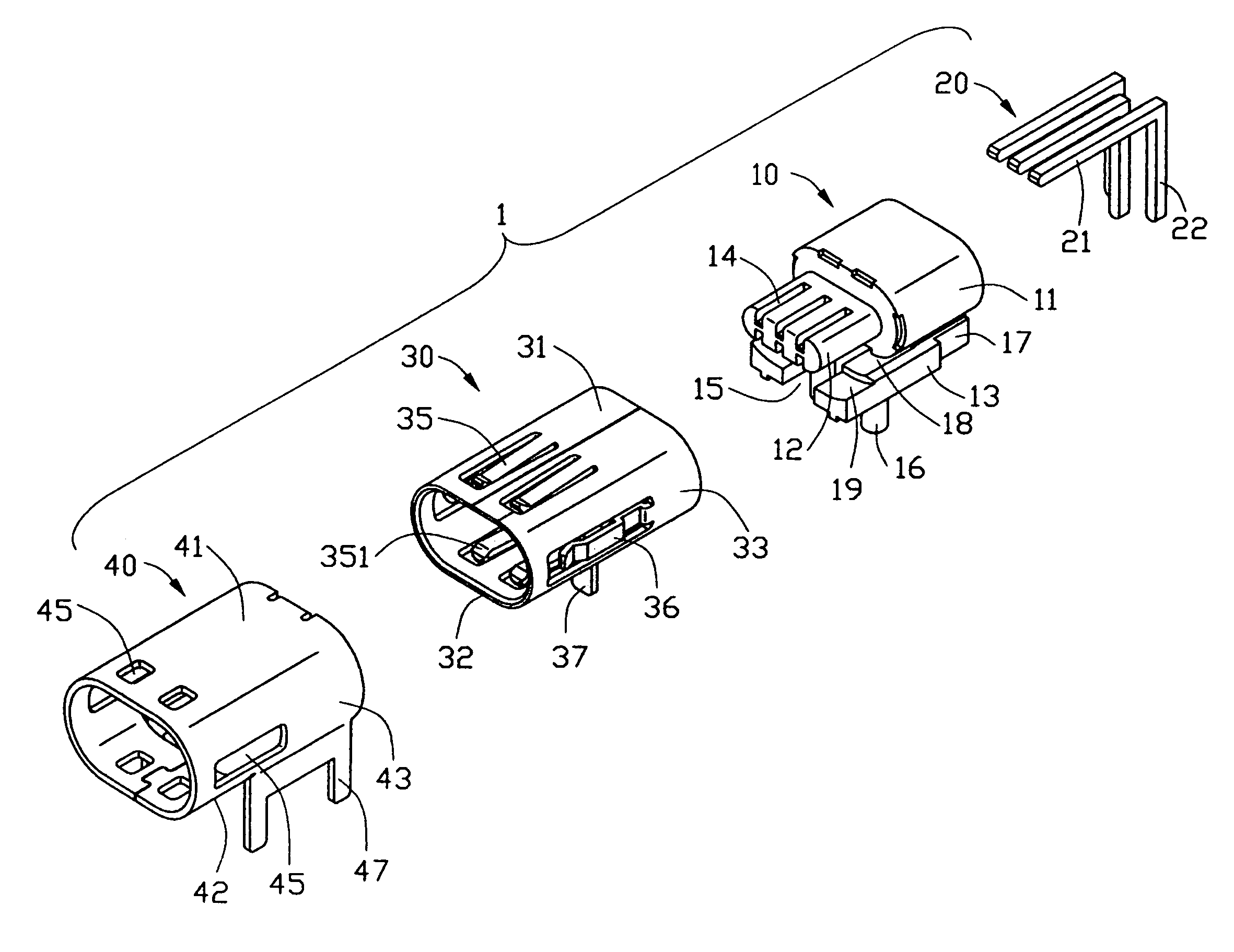
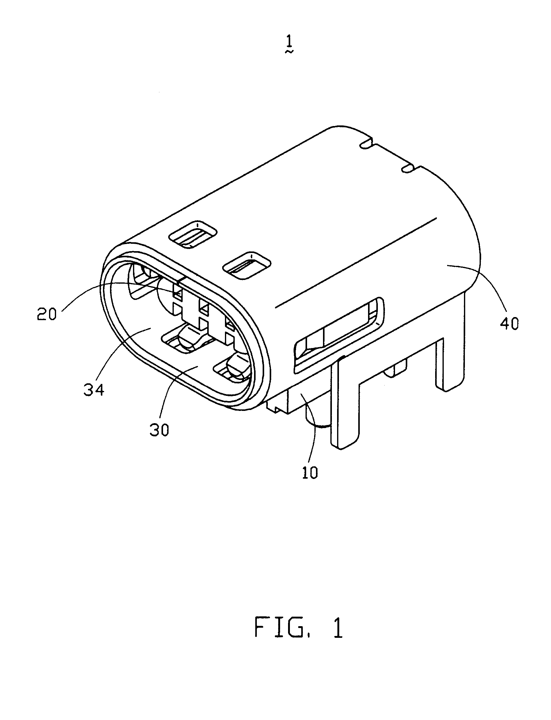
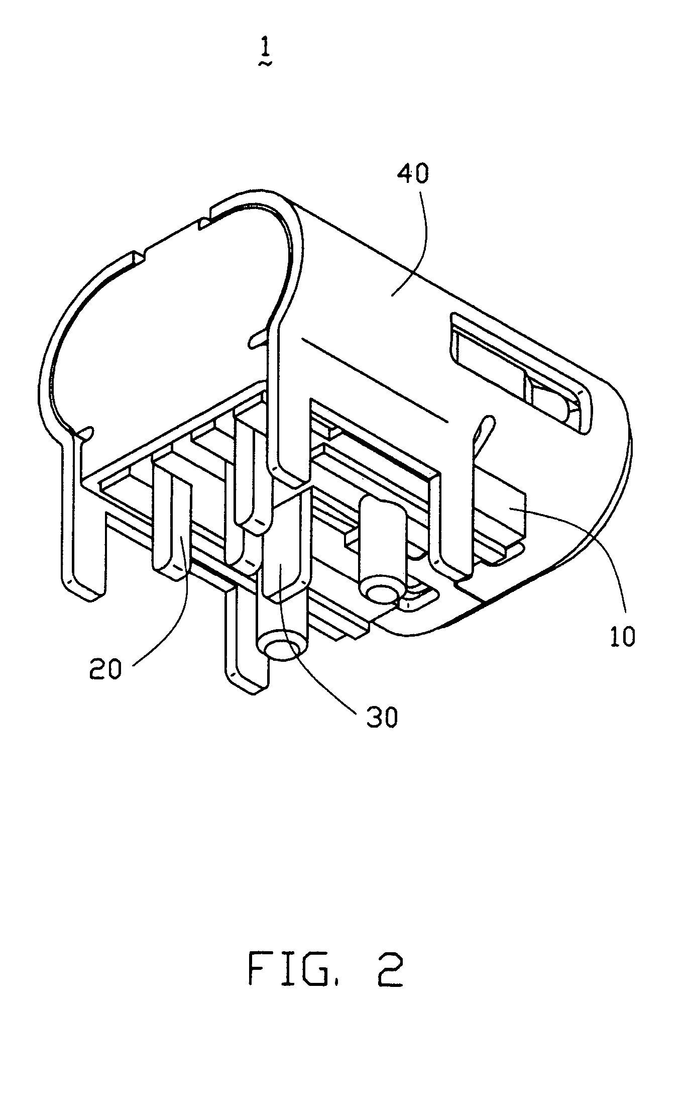
[0015]With reference to FIGS. 1 to 4, an electrical connector in accordance with the present invention is a power jack connector 1 mounting on a printed circuit board (not shown) and comprises an insulating housing 10, a plurality of contacts 20, an inner shell 30 and an outer shell 40.

[0016]The insulative housing 10 comprises a base portion 11 with an approximately elliptic cross-section, a tongue portion 12 with an approximately elliptic cross-section extending forwardly from the base portion 11 and a mounting portion 13 extending downwardly from the base portion 11. A plurality of passageways 14 extend through the base portion 11 along a longitudinal direction, and through the tongue portion 12 and the mounting portion 13 along a vertical direction. The mounting portion 13 comprises a recess 15 defined on a front end thereof, a pair of engaging portions 17 defined on opposite sides...


PUM


Abstract

An electrical connector (1) has an insulative housing (10), a plurality of contacts (20) received in the housing, an inner shell (30) surrounding the housing and an outer shell (40) surrounding the inner shell. The connector has a plurality of tabs (251, 263) extending inwardly therefrom. The tabs are constructed in the cover and bottom of the inner shell and can be latched to a mating connector. The out shell is conjoint to and overlaps the inner shell.

Description

BACKGROUND OF THE INVENTION[0001]1. Field of the Invention[0002]The present invention generally relates to an electrical connector, and particularly relates to a power connector mounting on a printed circuit board.[0003]2. Description of Prior Arts[0004]U.S. Pat. No. 6,139,350 discloses a shelled plug-in connector has an insulative housing, which, in the plug-in region, is constructed as a plastic tongue with an essentially rectangular cross-section. The connector has a shroud surrounding the tongue. The connector has two pairs of latching hooks with the hooks of each pair being alongside each other and being offset inwards, which hooks are constructed in the cover and bottom of the shroud and can be latched into recesses of a screening housing of a plugged-in mating connector. The upper side of the plastic tongue has two depressions, into which in each case one of the two upper latching hooks penetrates from above.[0005]Obviously, the latching hooks of the shroud result in two pair...

Claims


Application Information

Patent Timeline
Patent Type & Authority Patents(United States)
IPC IPC(8): H01R13/648H01R12/16
CPCH01R12/7088H01R23/6873H01R12/716H01R13/658
Inventor CHEN, WEI-XINGZHUANG, QUANWANG, NINGCHEN, ZHI-QIANGXUE, YA-LEI
Owner HON HAI PRECISION IND CO LTD
Learn More