Hard disk drive calibration method and apparatus

a hard disk drive and calibration method technology, applied in the direction of driving/moving recording heads, recording information storage, instruments, etc., can solve the problems of inability to read the servo information recorded on the disk b>1/b>, and inability to calculate the velocity of the head, etc., to achieve simple and accurate calibration methods.

Inactive Publication Date: 2006-05-09
SAMSUNG ELECTRONICS CO LTD
View PDF12 Cites 17 Cited by
  • Summary
  • Abstract
  • Description
  • Claims
  • Application Information

AI Technical Summary

Benefits of technology

[0047]Embodiments of the present invention provide a simple, accurate calibration method.

Problems solved by technology

For example, in a ramp loading / unloading type hard disk drive, the head is not located on the disk before the head is loaded on the disk or after the head is unloaded from the disk since the servo information recorded on the disk cannot be read, it is impossible to calculate the velocity of the head.
Therefore, the servo information recorded on the disk 1 cannot be read, and it is impossible to calculate the velocity of the head.
However, an additional temperature sensor is needed, which is disadvantageous.
In addition, it is very difficult to measure the temperature of only the VCM coil.
However, since the temperature of the VCM coil changes with the current through the VCM coil, the gain Gb of the VCM current amplifier 208b and the slope S reset based on the operational temperature of the hard disk drive are very inaccurate.
However, in the method, the head slider 4 must impact on the ICS, which may lead to an undesirable result.
Therefore, it takes a long time to perform the unloading operation.

Method used


Image

  • Hard disk drive calibration method and apparatus
  • Hard disk drive calibration method and apparatus
  • Hard disk drive calibration method and apparatus

Examples


Embodiment Construction

[0062]Reference will now be made in detail to embodiments of the present invention, examples of which are illustrated in the accompanying drawings, wherein like reference numerals refer to the like elements throughout. The embodiments are described below in order to explain the present invention by referring to the figures.

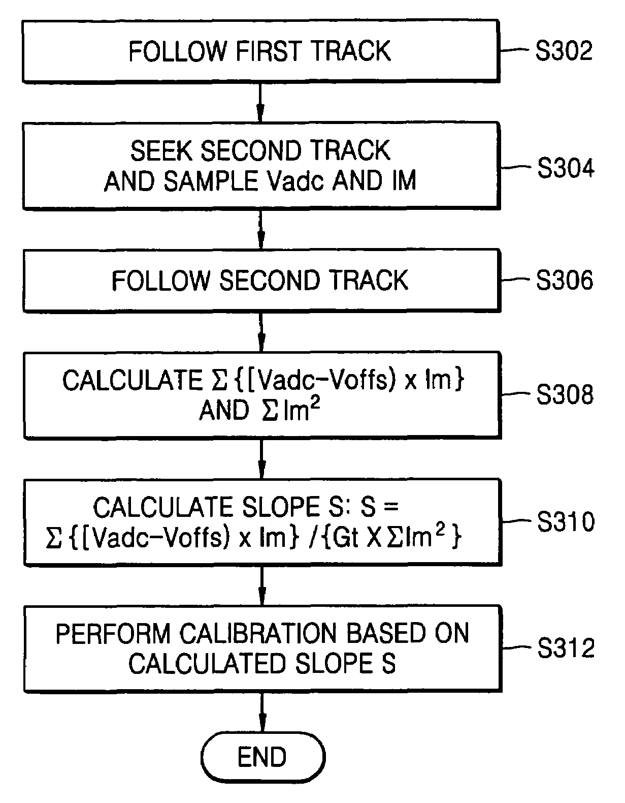
[0063]In an embodiment of the present invention, a slope S can be corrected by performing a single seek servo operation. In a conventional method, the slope S is corrected by repeatedly performing a plurality of seek servo operations. In comparison to the conventional method, the calibration method according to an embodiment of the present invention can accurately correct the slope S by performing the seek servo operation only once. In addition, according to an embodiment of the present invention, the calibration of the slope S can be obtained by performing even a short-distance seek operation because the seek distance is not related to the calibration of the slop...


PUM

PropertyMeasurementUnit
currentaaaaaaaaaa
voltageaaaaaaaaaa
coil resistance Rmaaaaaaaaaa

Abstract

A method of calibrating parameters of an apparatus for measuring a back electromotive force (BEMF) of a voice coil motor (VCM) for moving a head on a disk, the apparatus including the VCM having a coil resistance Rm, a coil inductance Lm, and a sensing resistance Rs, including: controlling the VCM to sequentially perform a track following operation of the head on a first track, a transferring operation of the head from the first track to a second track, and a track following operation of the head on the second track; sampling a differential voltage Vadc between a voltage across the VCM and a voltage across the sensing resistance Rs and a VCM driving current Im during the transferring operation; calculating a slope S based on a ratio of a first integration value to a second integration value, where the first integration value is obtained by integrating a product of the sampled differential voltage Vadc and the VCM driving current Im during the transferring operation, the second integration value being obtained by integrating a square of the VCM driving current Im during the transferring operation, the slope S being defined by the equation S=Rm−Gb×Rs, Gb being a gain of an amplifier for amplifying the voltage across the sensing resistance Rs; and calibrating the parameters of the apparatus using the slope S.

Description

CROSS-REFERENCE TO RELATED APPLICATION[0001]This application claims the priority of Korean Patent Application No. 2003-90560, filed on Dec. 12, 2003, in the Korean Intellectual Property Office, the disclosure of which is incorporated herein by reference.BACKGROUND OF THE INVENTION[0002]1. Field of the Invention[0003]The present invention relates to a hard disk drive calibration method and apparatus, and more particularly, to a method of calibrating parameters used to measure a back electromotive force (BEMF) of a voice coil motor (VCM), a method for measuring a BEMF of a voice coil motor, and an apparatus therefore.[0004]2. Description of Related Art[0005]In order to accurately control a seek operation of a hard disk drive, it is necessary to detect a velocity of a head. The velocity of the head is calculated by using servo information recorded on a surface of a disk of the hard disk drive. More particularly, the velocity of the head is calculated by using track numbers and sector n...

Claims


Application Information

Patent Timeline
Patent Type & Authority Patents(United States)
IPC IPC(8): G11B21/02G11B5/55G11B21/12G11B21/08G11B21/10H02P25/034H02P25/06
CPCG11B5/5534G11B21/10
Inventor JEONG, JUN
Owner SAMSUNG ELECTRONICS CO LTD
Why Eureka
Try Eureka