
Method for modelling an image device, corresponding computer program product and computer-readable carrier medium

a technology of image devices and carrier media, applied in image enhancement, instruments, optical elements, etc., can solve the problems of difficult to assess precisely, unreliable backward projection process, loss of depth information during acquisition process, etc., and achieve the effect of simple and accurate method of modelling and easy model establishment method

Active Publication Date: 2018-05-31
INTERDIGITAL CE PATENT HLDG
View PDF0 Cites 1 Cited by
  • Summary
  • Abstract
  • Description
  • Claims
  • Application Information

AI Technical Summary

Benefits of technology

The patent text describes a method for accurately modeling an imaging device using a simple approach that takes into account of its unique characteristics. This method is easier to establish than previous methods and can provide accurate results.

Problems solved by technology

Because a conventional image capture device acquires images which are projections from 3D scene onto a 2D plane (image sensor), depth information is lost during the acquisition process.
This model cannot respect the imaging system geometry (geometry of the sensor-lens-object triplets), making the backward projection process unreliable.
This model requires determining manually a high number of parameters, some of which are difficult to assess precisely (like the location of primary and secondary principal planes).
This kind of model is complex to implement in practice regardless of the optical formula of the optical system.

Method used


Image

  • Method for modelling an image device, corresponding computer program product and computer-readable carrier medium
  • Method for modelling an image device, corresponding computer program product and computer-readable carrier medium
  • Method for modelling an image device, corresponding computer program product and computer-readable carrier medium

Examples


Embodiment Construction

[0053]In all of the figures of the present document, identical elements are designated by the same numerical reference sign.

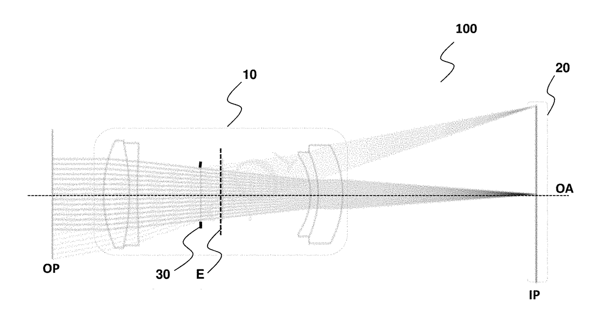
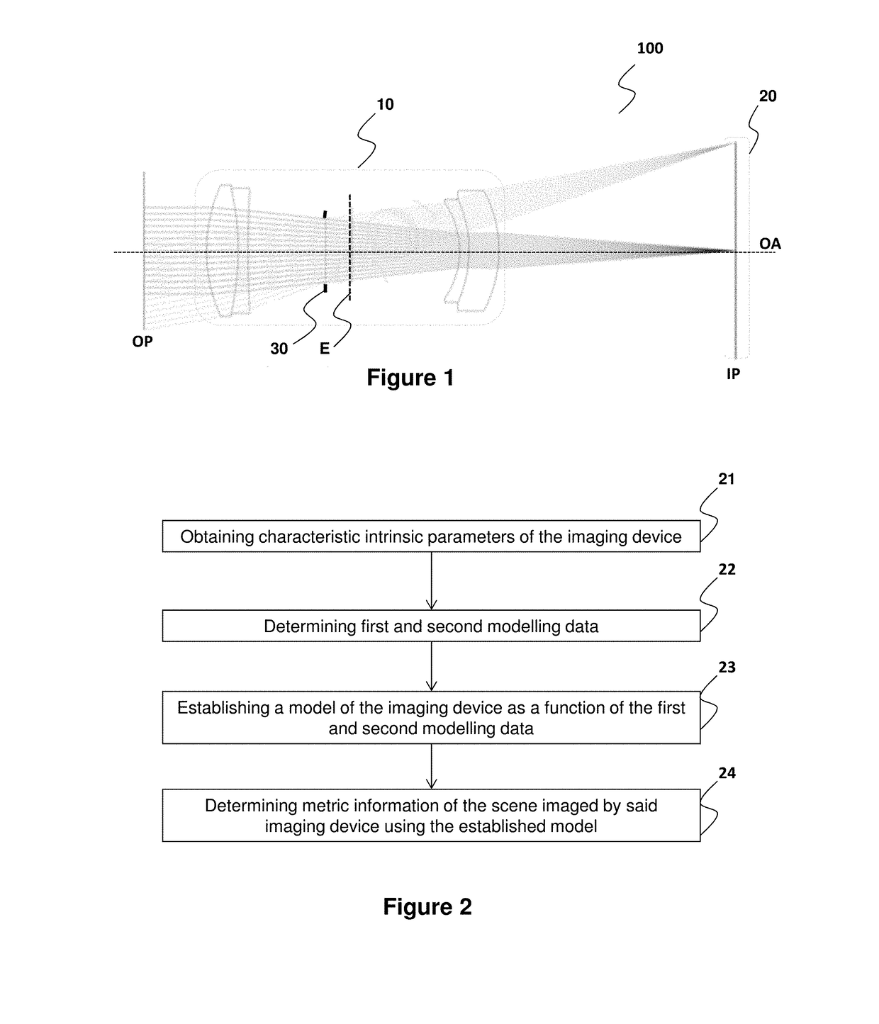
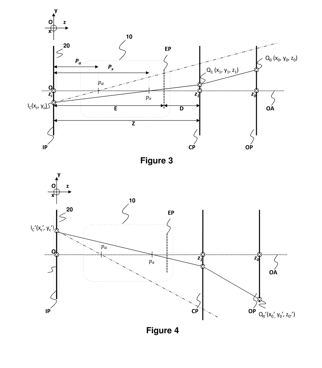
[0054]As it will be described more fully hereafter with reference to the accompanying figures, it is proposed in one aspect of the present disclosure to model an imaging device. This disclosure may, however, be embodied in many alternate forms and should not be construed as limited to the embodiments set forth herein. Accordingly, while the disclosure is susceptible to various modifications and alternative forms, specific embodiments thereof are shown by way of example in the drawings and will herein be described in detail. It should be understood, however, that there is no intent to limit the disclosure to the particular forms disclosed, but on the contrary, the disclosure is to cover all modifications, equivalents, and alternatives falling within the spirit and scope of the disclosure as defined by the claims. Like numbers refer to like elements throughout th...


PUM


Abstract

A method for modelling an imaging device including an image sensor and an optical system is disclosed. The optical system has an aperture iris diaphragm defining an entrance pupil of the optical system. For a given configuration of the imaging device the method includes estimating a set of characteristic intrinsic parameters of the imaging device, in which a first intrinsic parameter is representative of a distance between the image plane and a sensor conjugated plane conjugated to the image sensor with respect to the optical system; a second intrinsic parameter is representative of a distance between the sensor conjugated plane and the entrance pupil and a third intrinsic parameter is representative of a magnification of the optical system; determining first and second modelling data respectively as a function of the first and third intrinsic parameters and second and third intrinsic parameters; and establishing a model of the imaging device as a function of the second and third modelling data.

Description

1. REFERENCE TO RELATED EUROPEAN APPLICATION[0001]This application claims priority from European Patent Application No. 16306565.9, entitled “METHOD FOR MODELLING AN IMAGING DEVICE, CORRESPONDING COMPUTER PROGRAM PRODUCT AND COMPUTER-READABLE CARRIER MEDIUM”, filed on Nov. 28, 2016, the contents of which are hereby incorporated by reference in its entirety.2. TECHNICAL FIELD[0002]The present disclosure pertains to imaging device modelling.[0003]The present disclosure relates to a method for modelling an imaging device, notably but not exclusively, intended to dimensional measurement applications and tridimensional rendering.[0004]For the purposes of this disclosure, “imaging device” or “camera” shall mean an optical imaging system comprising an image sensor and an optical system which is used to form an image of a scene onto the photosensor.3. BACKGROUND[0005]The present section is intended to introduce the reader to various aspects of art, which may be related to various aspects of...

Claims


Application Information

Patent Timeline
Patent Type & Authority Applications(United States)
IPC IPC(8): G06T7/80G06T7/50
CPCG06T7/80G06T7/50G06T2207/10028G02B27/0012G06F30/20G06T15/005G06T15/205G06T7/30
Inventor DRAZIC, VALTERBLONDE, LAURENTKERBIRIOU, PAULBURELLER, OLIVIERBOISSON, GUILLAUME
Owner INTERDIGITAL CE PATENT HLDG
Learn More