Calibration system with at least one camera and method thereof

a technology of a calibration system and a camera, applied in the field of calibration systems and methods, can solve the problems of manual operation, method is still too cumbersome, machine precision exceeds the limits of manual operation, etc., and achieves the effect of a simple and more accurate calibration method and a simpler and more accurate calibration system

Active Publication Date: 2019-06-27
ADVANCED ION BEAM TECHNOLOGY INC
View PDF7 Cites 0 Cited by
  • Summary
  • Abstract
  • Description
  • Claims
  • Application Information

AI Technical Summary

Benefits of technology

[0022]By the step of providing a first actuator to move the first element an increment along a first direction and comparing the first picture and the second picture to calibrate the first element, the method for calibrating element according to an embodiment of the present invention can carry on calibration automatically and carry on calibration in vacuum environment and provide a simpler and more accurate calibrating method. By providing a camera used for taking pictures of a first element

Problems solved by technology

Although the methods of adjusting is announced, but these methods are still too cumbersome and require manual operations for calibration.
However, with the m

Method used


Image

  • Calibration system with at least one camera and method thereof
  • Calibration system with at least one camera and method thereof
  • Calibration system with at least one camera and method thereof

Examples


Embodiment Construction

[0032]The embodiments of the invention will be described below with reference to the drawings. It should be understood that the specific embodiments described herein are merely illustrative of the invention and are not intended to limit the invention. The figures reveal some details. It should be understood that the details of the figures may be different from those that have been disclosed in words unless explicitly limiting the characteristics in specification.

[0033]In the description, it should be understood that the terms “longitudinal”, “horizontal”, “upper”, “lower”, “front”, “rear”, “left”, “right”, “Horizontal”, “top”, “bottom”, “inside”, “outside” and the like are based on the orientation or positional relationship shown in the drawings only for the purpose of describing the invention, it is not instructions or implied means that the device or element must have a specific orientation, constructed and operated in a particular orientation, and therefore it should not be const...


PUM


Abstract

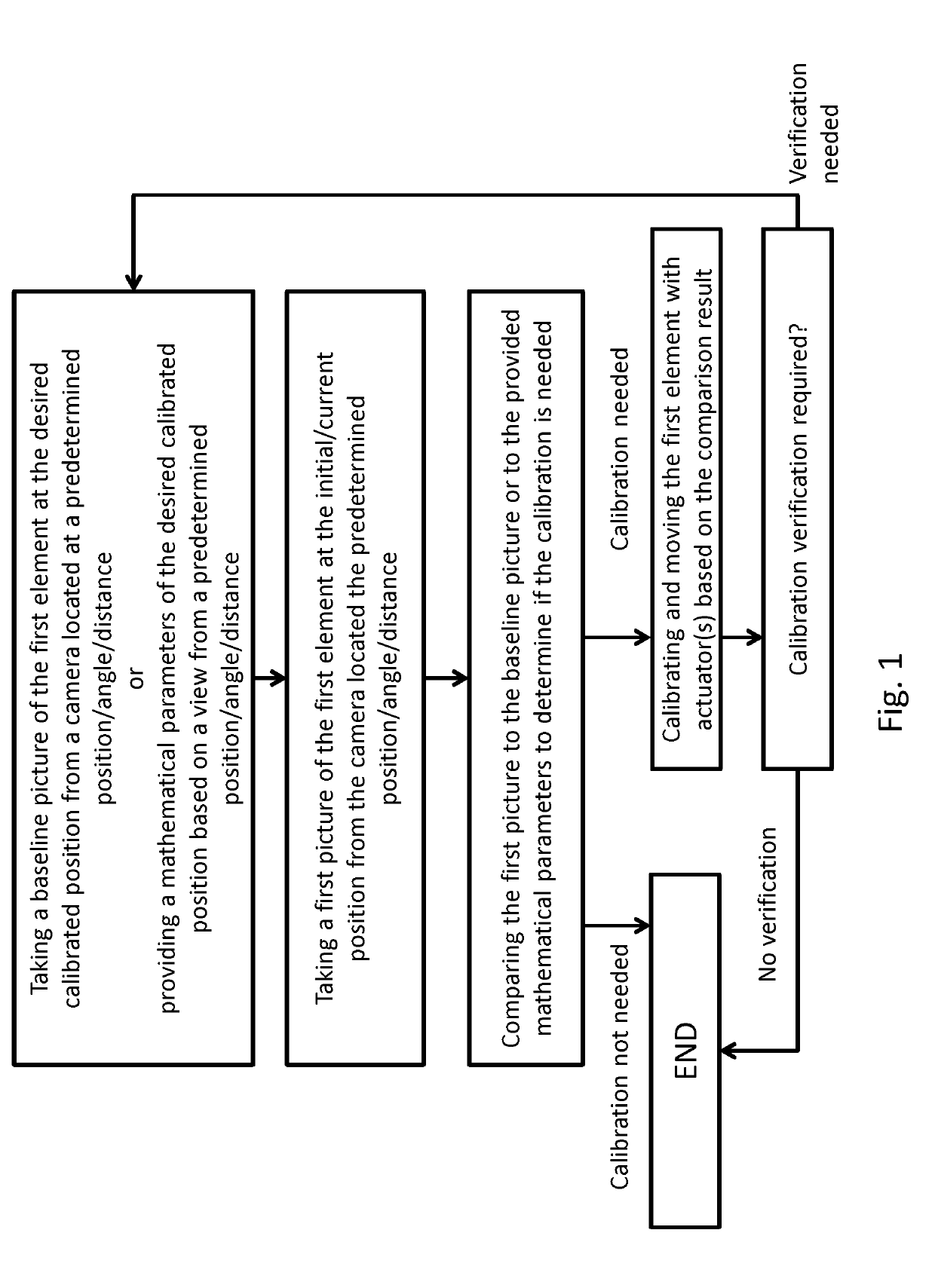
A method for calibrating element in a semiconductor processing device with a camera is provided. The method for calibrating element in a semiconductor processing device with a camera includes taking a first picture of a first element by a camera; providing a first actuator to move the first element an increment along a first direction; taking a second picture of the first element by the camera; and comparing the first picture and the second picture to calibrate the first element. A system for calibrating element in a semiconductor processing device with a camera is also provided.

Description

BACKGROUND OF INVENTION[0001]The present invention is related to a calibration system and method, and more particularly to a calibration system and method with a camera.[0002]In semiconductor processing, the dimension of circuit is more and more scaling down, and the requirement of precision of the production equipment is higher and higher. In order to improve the quality of integral circuit and accuracy of the semiconductor process, the positioning of each component inside the production equipment must be very precise. U.S. Pat. No. 6,633,046 B1 disclosed a method and apparatus for detecting that two moveable members are correctly positioned relatively to one another. U.S. Pat. No. 8,519,363 B2 disclosed a wafer handling method and an ion implanter that are capable of accurately adjusting a twist angle of a wafer to a target twist angle given as one of ion implantation conditions. Although the methods of adjusting is announced, but these methods are still too cumbersome and require...

Claims


Application Information

Patent Timeline
IPC IPC(8): G06T7/00H01L21/68G06T7/73
CPCG06T7/001H01L21/681G06T7/74G06T2207/30164G06T2207/30148G06T2207/10016
Inventor CHEN, CHIEN-LINI, YU-HOKUO, CHIEN-CHENGWANG, TE-MIN
Owner ADVANCED ION BEAM TECHNOLOGY INC
Why Eureka
Try Eureka