
Image processing apparatus, image processing method, and storage medium

a technology of image processing and image processing method, which is applied in the field of image processing apparatus, image processing method and storage medium, can solve the problems of inability to employ process, inability to use process, and large load on the operator, and achieve the effect of easy and correct extraction of a specific obj

Inactive Publication Date: 2006-07-11
CANON KK
View PDF20 Cites 17 Cited by
  • Summary
  • Abstract
  • Description
  • Claims
  • Application Information

AI Technical Summary

Benefits of technology

[0015]To resolve the above shortcomings, it is a first objective of the present invention to easily and correctly extract a specific object from an image.
[0016]It is a second objective of the present invention to permit the partial authentication of an outline so as to provide a simple and accurate process for extracting an object from an image, which used to impose a great load for an operator.
[0017]It is a third objective of the present invention to permit an operator to freely change an outline extraction in accordance with local image characteristics so as to improve the accuracy with which an object is extracted from an image.

Problems solved by technology

In this case, the results of the process can not be employed.
If, however, the area having the same density or the same color is extended and enters the object, the results of the process can not be employed.
The optimal setup for the permissible range for determining an area having the same density or the same color requires an experienced operator and the performance of repeated trials, which places a great load on the operator.
In addition, in many cases the outline of an object does not completely match the boundary of the selected area according to which the permissible range is set.
Therefore, the employment of a permissible range is limited to images having a flat background, or to an object having the same density or a single color.
This, too, places a great load on the operator.
Since depending on the part of an object the correct parameter will differ, even if one part of the enclosure line matches the outline of the object, an overall match can not be acquired, and a desired outline can not be extracted.
In addition, this method is hard to apply for an image that includes a complicated background.

Method used


Image

  • Image processing apparatus, image processing method, and storage medium
  • Image processing apparatus, image processing method, and storage medium
  • Image processing apparatus, image processing method, and storage medium

Examples


first embodiment

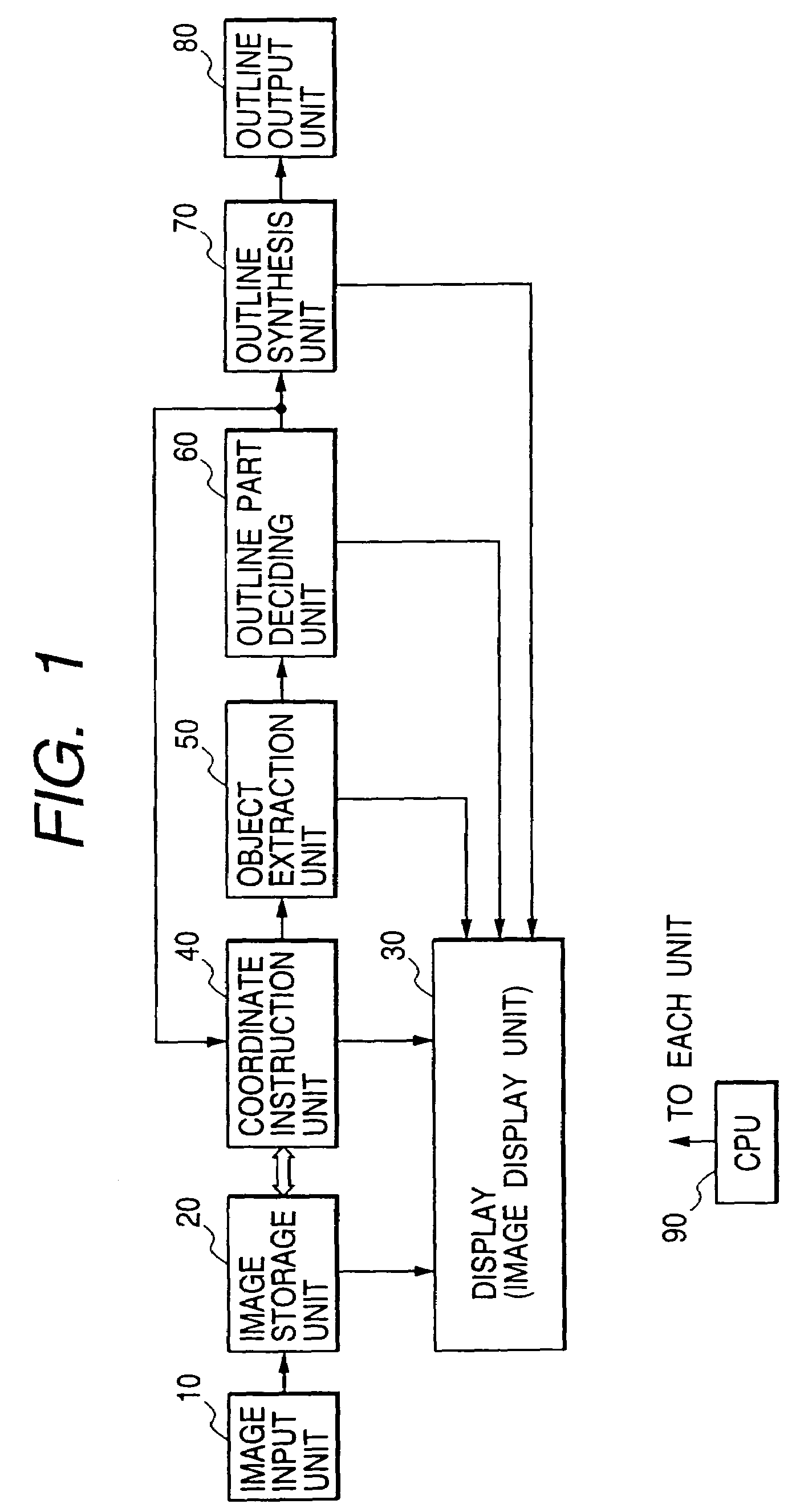
[0046]FIG. 1 is a functional diagram that presents a representation of most of the characteristics of a first embodiment. The arrangement shown at the bottom is implemented by a personal computer or a workstation. In FIG. 1, an image input unit 10 is an input unit, such as a scanner, a digital camera or a digital VTR (VCR), that has a pickup function, or an input unit for reading recorded image data from a storage medium, such as a CD-ROM, an MO, a compact flash memory or a hard disk, and supplying the image data to the image input unit 10. An image storage unit 20 is used to store an input image. An image display unit 30 is a CRT or a liquid crystal display for displaying an input image. A coordinate instruction unit 40 is a mouse or a keyboard for designating arbitrary coordinates or an arbitrary area in an image that is displayed. And an object extraction unit 50 extracts a specific object from an image.

[0047]An outline part deciding unit 60 selects a part of an outline of an obj...

second embodiment

[0077]FIG. 7 is a flowchart showing the processing for a second embodiment of the present invention. The primary difference from the first embodiment in FIG. 2 is the addition of steps 700 and 710. At step 700, an object extraction unit is selected, and at step 710, a check is performed to determine whether the currently used object extraction unit should be changed or should continue to be employed.

[0078]An explanation will now be given, while referring to FIG. 8, for the processing performed to switch between the use of the above three types as the object extraction method.

[0079]FIG. 8 is a diagram showing the state wherein the operator extracts an object while switching between the three types of object extraction methods shown in FIGS. 3 to 5.

[0080]In FIG. 8, an object 800 is the one to be extracted; an enclosure line 810 is a line described to enclose the object 800; a closed area 820 is an area regarded as evincing same quality (e.g., the same color or the same density) as a d...

third embodiment

[0083]According to the first and the second embodiments, the operator, for example, determines when to terminate step 140 for the authentication of the outline segments by the outline part deciding unit 60, and after step 140, the outline segments are collectively synthesized at step 160. In the third embodiment, step 140, for authentication of the outline segments, and step 160, for the synthesis of the outline segments, are directly connected together to automatically determine the end of the outline part of the authentication step.

[0084]FIG. 9 is a flowchart showing the processing performed for the third embodiment. In FIG. 9, the termination decision step 150 in FIGS. 2 and 7 is deleted, and the use of the outline part authentication step 140 and the outline synthesis step 160 is continued. Further, step 900 for determining whether a closed curve has been completed and step 910 for determining whether an outline should be corrected after the closed curve has been completed are a...


PUM


Abstract

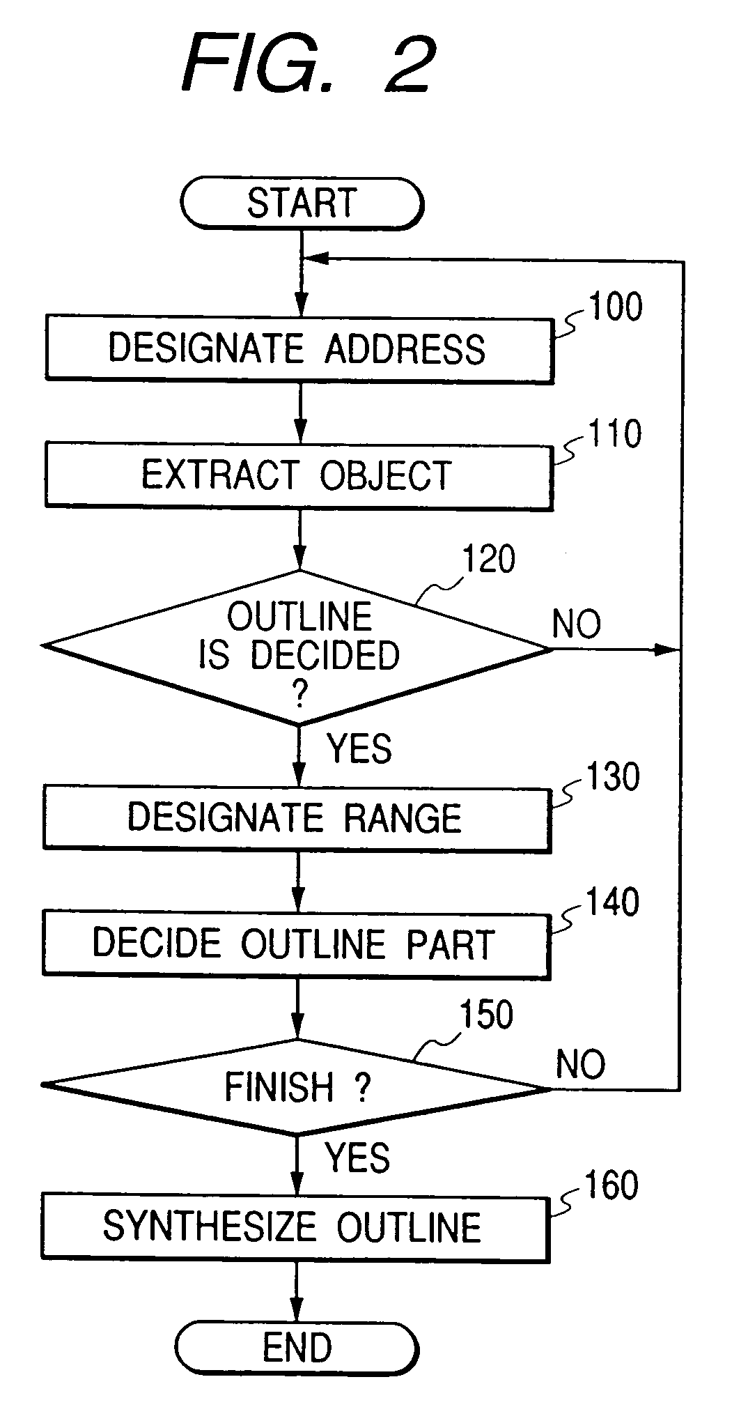
The objective of the present invention is to provide a simple and accurate process for extracting an object from an image, which is used to impose a great load for an operator. According to the present invention, an image processing apparatus comprises an object extracting unit, for performing a predetermined process for image data for a position or an area that is designated and for extracting a specific object from an image, an outline part deciding unit, for selecting and authenticating an arbitrary segment of an outline obtained by the extracting unit, and an outline synthesis unit, for linking and synthesizing together the outline segments that are authenticated. Since a closed curve is formed by synthesizing the outline segments obtained by repeating the above process, and the outline of the object is thus determined, the outline segment that is extracted from the image and matches the correct outline of the object is sequentially selected and authenticated. The thus authenticated outline segments are linked and synthesized to gradually form the overall outline of the object.

Description

[0001]This application is a divisional of application Ser. No. 09 / 363,655, filed Jul. 30, 1999 which is now U.S. Pat. No. 6,674,902 issued on Jan. 6, 2004.BACKGROUND OF THE INVENTION[0002]1. Field of the Invention[0003]The present invention relates to an image processing apparatus, an image processing method and a storage medium.[0004]2. Related Background Art[0005]Roughly three different technique types are employed to extract a specific object from an image:[0006]1. the object extraction type, for sequentially selecting areas having the same density or the same color using an area division method that employs the color tones of an image, the texture (pattern) and color information, and for extracting an object from each area.[0007]2. the outline tracing type, whereby an operator sequentially traces the outline of an object and extracts the object along a tracing locus, whereby an edge is detected in the vicinity of the tracing locus and an object is extracted along the edge, or wh...

Claims


Application Information

Patent Timeline
IPC IPC(8): G06K9/46G06T5/00
CPCG06T7/0083G06T2207/20104G06T2207/30196G06T2207/20144G06T2207/20168G06T2207/20136G06T7/12G06T7/181G06T7/194
Inventor KONDO, TOSHIAKIMATSUGU, MASAKAZUTAKAHASHI, FUMIAKI
Owner CANON KK
Learn More