Multiphase flowmeter using a combination of pressure differentials and ultrasound doppler readings

a multi-phase flowmeter and ultrasound doppler technology, applied in the direction of volume/mass flow measurement, measurement devices, instruments, etc., can solve the problems of not being able to meet satisfactorily all the requirements, not being able to fully accept radioisotope-based methods, and not being able to handle the many flow and fluid conditions of multiple devices. achieve the effect of simple and accura

Active Publication Date: 2010-08-12
MEDENG RES INST
View PDF8 Cites 16 Cited by
  • Summary
  • Abstract
  • Description
  • Claims
  • Application Information

AI Technical Summary

Benefits of technology

[0012]The present invention does not make use of any radioactive sources. The present invention is simple, accurate with measurement stability and repeatability.

Problems solved by technology

Various devices are used in the industry, however none is considered capable of meeting satisfactorily all the requirements that are posed by wide ranging set of field conditions in the industry.
No single device handles the many flow and fluid conditions that are encountered due to both geological conditions and industrial methods of extraction, and / or meets the precision requirements over the full extent of the large range of flow rates, water cut, and gas fraction that occur in the field.
In addition, several devices make use of radioactive sources, which hold significant disadvantages.
The use of these sources imposes careful and important containment requirements to mitigate the possibility of contamination, and as a result the industry is reluctant to fully accept methods making use of radioisotopes.
The equipment, called separators, is generally large, difficult to install and relatively costly.
Room for improvement of the achievable precision inherent to this method is therefore limited.
However, because the method used by such devices is sensitive to interferences in flow regimes and in patterns of multiphase flow, the stability of the measurements represent an issue that is not fully resolved by the technology.
In addition, in many areas of the world the water fraction contained in the fluid is disturbed with varying degrees of salinity, affecting the density of the water and the precision of measurements that use impedance / capacitance techniques.
The structure of the MPFMs in this category is generally complex and costly.
The calibration, installation and maintenance all poses significant operational challenges to the industry.

Method used


Image

  • Multiphase flowmeter using a combination of pressure differentials and ultrasound doppler readings
  • Multiphase flowmeter using a combination of pressure differentials and ultrasound doppler readings
  • Multiphase flowmeter using a combination of pressure differentials and ultrasound doppler readings

Examples


Embodiment Construction

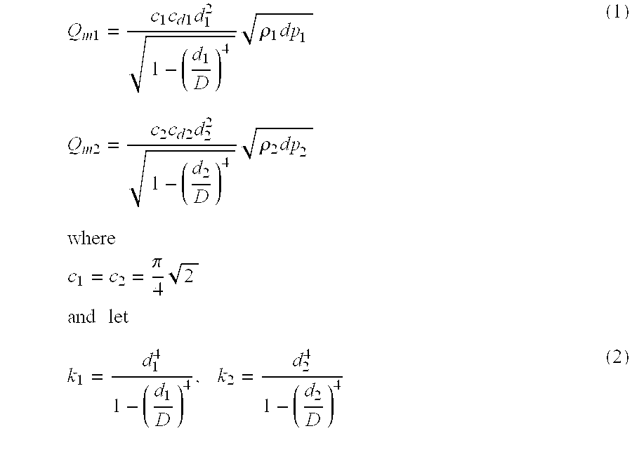
[0033]The following parameters are defined for use in the equations that follow in this description:

[0034]cd1=flow rate coefficients of orifice plate 1

[0035]cd2=flow rate coefficients of orifice plate 2

[0036]D=diameter of uniform pipe

[0037]d1=inner diameter of orifice plate 1

[0038]d2=inner diameter of orifice plate 2

[0039]dp1=pressure differential at orifice plate 1

[0040]dp2=pressure differential at orifice plate 2

[0041]n1=gas liquid ratio (GLR)

[0042]QS=flow rate obtained with the ultrasound Doppler

[0043]QL1=flow rate of liquid

[0044]Qm1=mass flow rate at orifice plate 1

[0045]Qm2=mass flow rate at orifice plate 2

[0046]Q1=volume flow rate at orifice plate 1

[0047]Q2=volume flow rate at orifice plate 2

[0048]Qg1=gas phase volume flow rate

[0049]Qw1=water phase volume flow rate

[0050]Qo1=oil phase volume flow rate

[0051]ρ1=density of total mixture at orifice plate 1

[0052]ρ2=density of total mixture at orifice plate 2

[0053]WR1=water cut

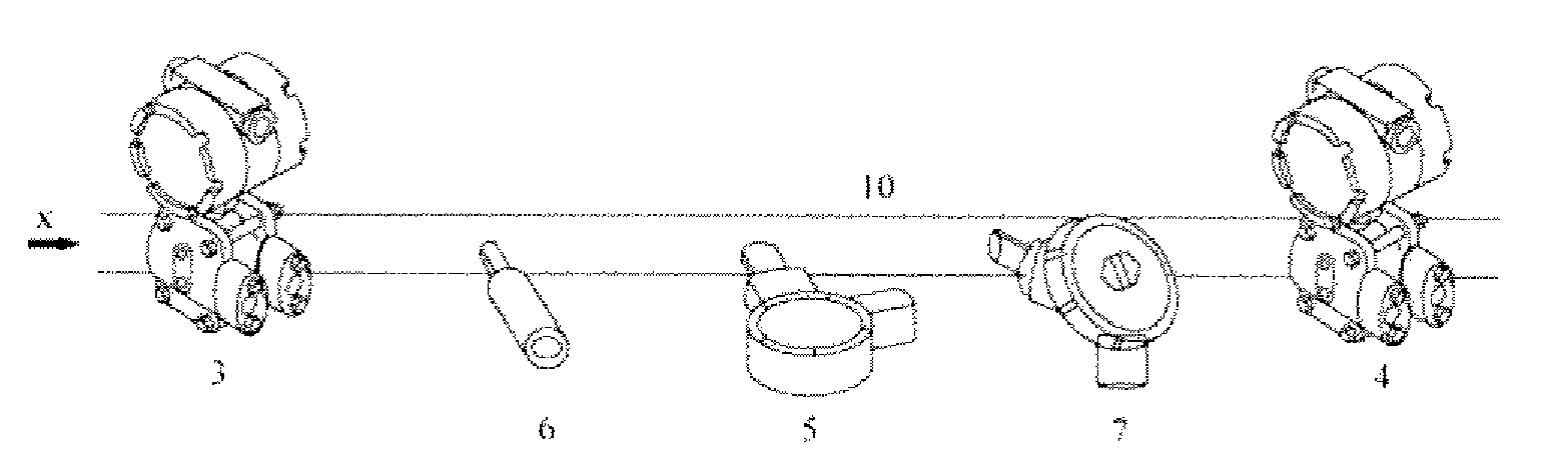
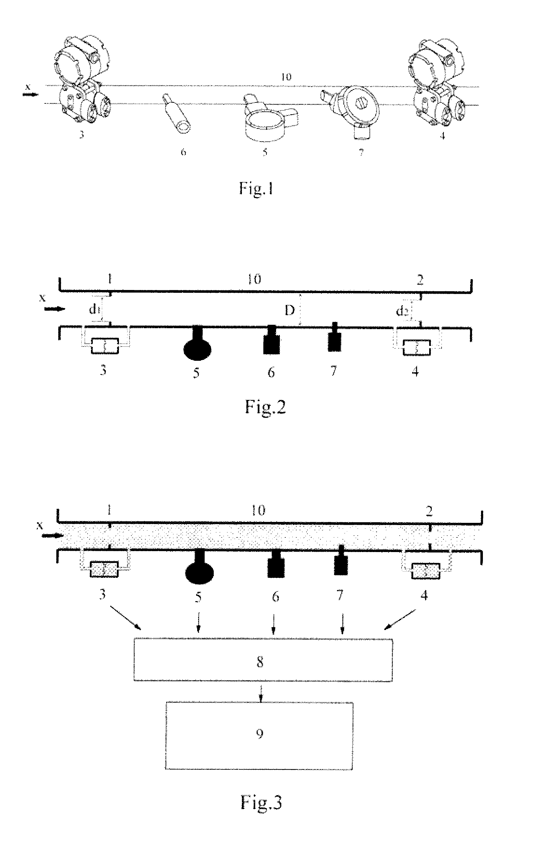
[0054]Reference is made to FIG. 1 of the drawings which d...


PUM


Abstract

A multiphase flowmeter, and a method of analyzing and measuring multiphase flow is described. The body of the multiphase flowmeter consists of the following components. It has a straight flow pipe in which two orifice plates a lodged near the extremities. At each of these two locations, a pressure differential transmitter measures the pressure drop that occurs as the fluid passes through the orifice plates. Along the length between the orifice plates, an ultrasound Doppler sensor measures the volume flow rate of the multiphase fluid, a pressure transmitter measures the in-pipe pressure and a temperature sensor measures the temperature. From the signals obtained from the above sensors, an overall analysis of the multiphase fluid flow is performed providing a complete set of flow measurement data for the mixture and for each of the three phases consisting of oil, water and gas.

Description

FIELD OF INVENTION[0001]The present invention relates to an apparatus and method of analysis for the measurement of a multiphase fluid flow. The invention is particularly, but not exclusively, suitable for measuring the flow of multiphase fluids that are produced in oil and gas wells, on shore and off shore installations, pipe lines and in refineries.BACKGROUND OF THE INVENTION[0002]The oil and gas industry is increasingly calling for the development of a new technology that is compact, light weight and most importantly affordable, which can be installed “in-line” and produce a complete set of accurate measurements on each component of multiphase flow.[0003]Various devices are used in the industry, however none is considered capable of meeting satisfactorily all the requirements that are posed by wide ranging set of field conditions in the industry. No single device handles the many flow and fluid conditions that are encountered due to both geological conditions and industrial metho...

Claims


Application Information

Patent Timeline
Patent Type & Authority Applications(United States)
IPC IPC(8): G01F1/74
CPCG01F1/363G01F1/74G01F1/663
Inventor LIU, ZHULIU, ZHAORONG
Owner MEDENG RES INST
Why Eureka
Try Eureka