Method for measuring HVAC efficiency

a technology of hvac efficiency and measurement method, which is applied in the direction of heating types, instruments, nuclear elements, etc., can solve the problems of reducing the efficiency of an hvac system, poor maintenance of ducts and equipment, and many residential systems do not have e/a or o/a options, so as to reduce the heat transfer between a heating coil and system air, accurately determine the volumetric flow rate, and increase the efficiency of the heating coil

Active Publication Date: 2015-08-20
ROCK LANCE
View PDF2 Cites 1 Cited by
  • Summary
  • Abstract
  • Description
  • Claims
  • Application Information

AI Technical Summary

Benefits of technology

[0013]For example, heat transfer between a heating coil and system air is reduced if the heating coils have become fouled with insulating particulates such as dirt. With the fan running and with all elements turned off, the HVAC system is run until it reaches steady state which is ordinarily fifteen or twenty minutes. The enthalpy is measured using any of a number of conventional instruments which are readily available at a point downstream of the heating coil. For best results, this downstream point is at a position where the temperature across a cross section of the duct varies less than 0.5 degrees F. The heating coil is then activated and the system again allowed to reach steady state. The enthalpy measured again at the same location, and the difference between the two enthalpy measurements is delta enthalpy due only to the heating coil. The temperature of the water entering and leaving the heating coil is measured along with the volumetric flow rate of the water passing through the heating coil. Using the well known formula and calculations described below, the enthalpy produced by the heating coil may be determined. If the heating coil were operating at design specifications, the delta enthalpy measured within the HVAC system should be equal to the enthalpy produced by the heating coil working fluid. The difference between the delta enthalpy and the enthalpy produced by the heating coil is a measure of the current effectiveness of the heating coil. Cleaning a dirty coil, for example, may increase the efficiency of the heating coil.
[0014]In a second embodiment of the instant invention the same measurements may be used to accurately determine the volumetric flow rate through the HVAC system in the treatment node. However, an additional measurement must be taken. Enthalpy must also be measured directly downstream of the supply duct. This method of measuring air flow in an HVAC system is believed to be much superior to the current method which involves measuring a pressure grid using a large number of measurements using a pitot tube of anemometer.
[0016]Another objective of the present invention is to provide a simple and accurate method for determining air flow within an HVAC system.
[0017]Another objective of the present invention to provide a method for quickly and easily determining whether a newly created or reworked HVAC system is operating within its design parameters or how much its performance has been improved.
[0018]Another objective of the present invention is to provide a method for measuring HVAC efficiency which is simple, reliable, inexpensive, and easy to use and maintain.

Problems solved by technology

Many residential systems do not have E / A or O / A options within the HVAC system.
Poor maintenance of ducts and equipment greatly reduces efficiency.
Clogged or dirty filters, heating coils, or cooling coils also greatly reduce the efficiency of an HVAC system.
However, it is believed to be nearly impossible at the current time to determine the operating efficiency of the various elements of an HVAC system, including filter, heating coil, and cooling coil separately with any accuracy.
For example, it is not currently possible to accurately measure the effect of changing the filter or filters.
At the current time it is even relatively difficult to determine the actual air flow within an HVAC system.
Using the current state of the art, it is very difficult to obtain correct measurements to either determine the efficiency of the elements of an HVAC system or even to determine the air flow through the system.
This method is expensive and time consuming because a large number of measurements to be taken; and it is not particularly accurate because the air is ordinarily not thoroughly mixed at this point in the system and human error often becomes a factor.
A significant portion of our total energy use is wasted by inefficient HVAC systems.
If, for instance, the cooling coil in an HVAC system is not cleaned or replaced when it should be or is cleaned or replaced when it isn't necessary, energy or money is wasted.
If an HVAC system is poorly designed or doesn't actually operate as well as it should considering the design parameters, energy is wasted.

Method used


Image

  • Method for measuring HVAC efficiency
  • Method for measuring HVAC efficiency
  • Method for measuring HVAC efficiency

Examples


Embodiment Construction

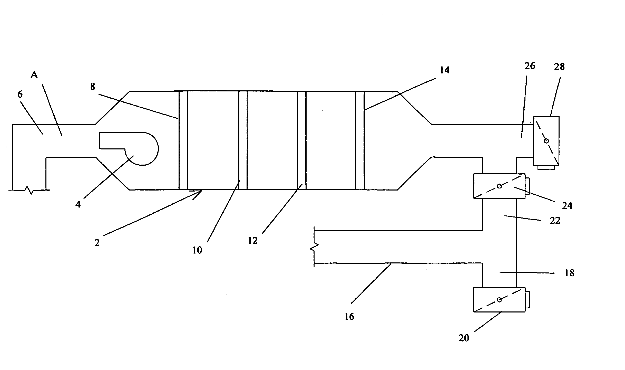
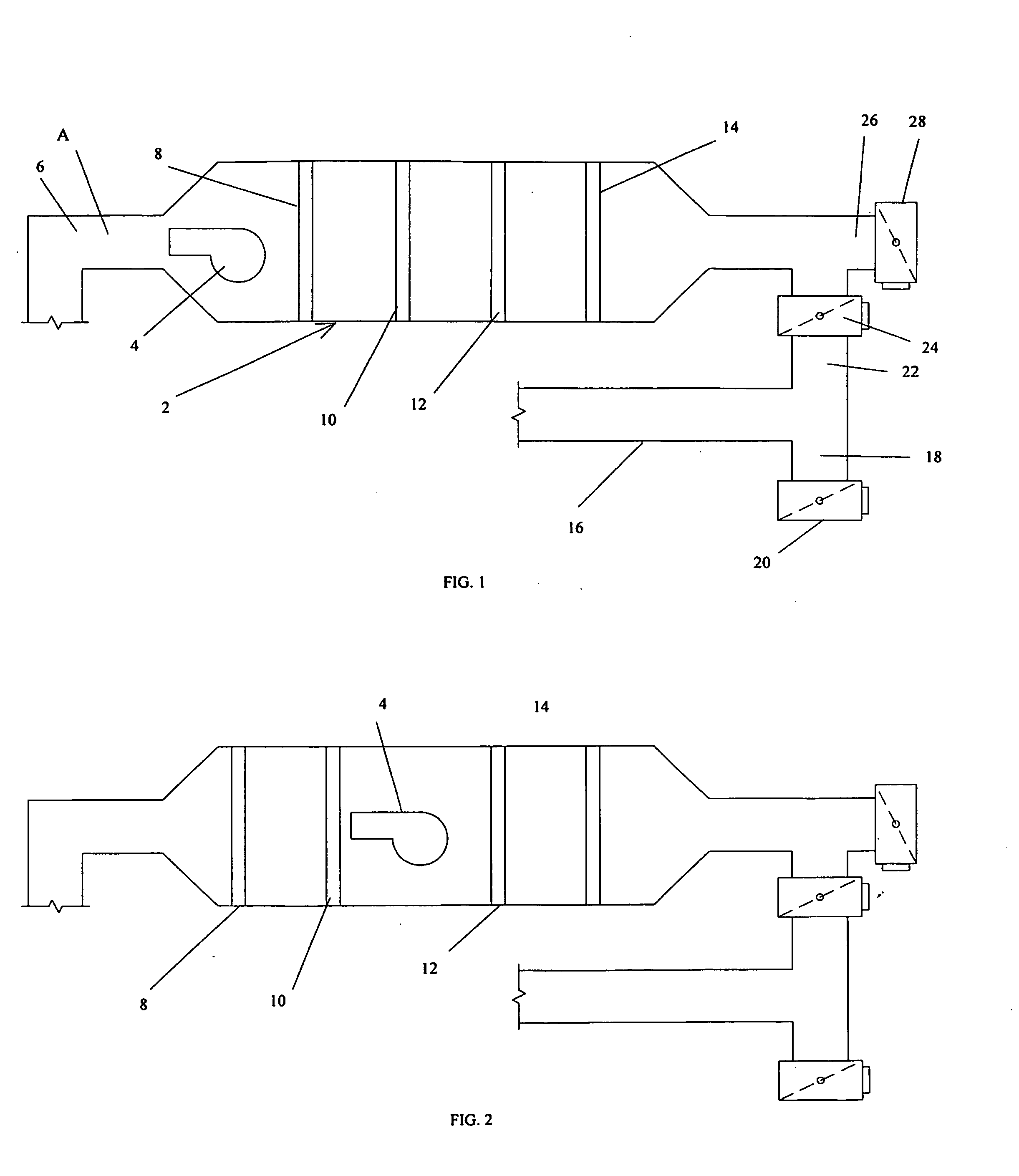
[0022]Referring to the drawings, FIGS. 1 and 2 there are shown schematic views of pull-through and push-through HVAC systems. These Figures are intended to be representative of typical HVAC systems and to show the most commonly found elements within those systems. It is the method of analysis of such systems which is considered to be the invention rather than the systems themselves. The method of the instant invention analyzes and evaluates various elements of such systems including, for example, heating coils, cooling coils, and filters; but the method should work equally well with any element which causes a change in the enthalpy of the system air between the upstream side of the element and the downstream side of the element.

[0023]Now referring to FIG. 1, a schematic view of a typical pull-through HVAC system is shown. A treatment node 2 is ordinarily located in an area which allows relatively easy access, but is usually totally enclosed inside a duct. A fan 4 is located near the...


PUM


Abstract

A method for measuring HVAC efficiency is disclosed which may be used to test various elements within the HVAC system to determine whether any element, such as a heating coil, is operating at an acceptable efficiency when compared to design specifications or previously established standards. The method may also be used to easily determine volumetric flow rate of air through the system at various points simply.

Description

RELATED APPLICATIONS[0001]This application is a continuation of U.S. patent application Ser. No. 12 / 800,017 filed on May 5, 2010 and further relies for priority upon Provisional Patent Application No. 61 / 175,790 filed on May 6, 2009.FIELD OF THE INVENTION[0002]The present invention relates generally to heating, air-conditioning, and ventilation (HVAC) systems and more specifically to a method for analyzing and measuring the efficiency of such systems.BACKGROUND INFORMATION[0003]Nearly every modem building has some form of HVAC system for heating, ventilation, air conditioning, and moving air within the building. An efficient, effective HVAC system is necessary not only for the comfort of the occupants of a building; but, has become increasingly clear relatively recently, for the mental and physical health of such occupants. Although there are many variations of HVAC systems, in general such systems include a variety of air ducts, at least one fan for moving air, a filter, a heating ...

Claims


Application Information

Patent Timeline
Patent Type & Authority Applications(United States)
IPC IPC(8): F24F11/00G01M99/00
CPCG01M99/005F24F11/0086F24F2140/20F24F11/32F24F11/30F24F11/49F24F11/46
Inventor ROCK, LANCE
Owner ROCK LANCE
Why Eureka
Try Eureka