Fixing mechanism of an electronic device

a technology of fixing mechanism and electronic device, which is applied in the direction of electrical apparatus casing/cabinet/drawer, instruments, computing, etc., can solve the problem of inconvenient structure and achieve the effect of simple and fast method of taking

Inactive Publication Date: 2006-05-16
FIRST INTERNATIONAL COMPUTER
View PDF4 Cites 4 Cited by
  • Summary
  • Abstract
  • Description
  • Claims
  • Application Information

AI Technical Summary

Benefits of technology

[0006]It is therefore a primary object of the invention to provide a fixing mechanism of an electronic device that offers a simpler and faster method to take the electronic device out of a computer when the electronic device mal functions.

Problems solved by technology

The DVD drive 2 is fixed on the computer and not easy to take apart; if the DVD drive 2 malfunctions and to be repaired, users have to dismantle the computer to take the DVD drive 2 from the computer, and then take the DVD drive 2 out from the frame 10 to repair, such structure is very inconvenient.

Method used


Image

  • Fixing mechanism of an electronic device
  • Fixing mechanism of an electronic device
  • Fixing mechanism of an electronic device

Examples


Embodiment Construction

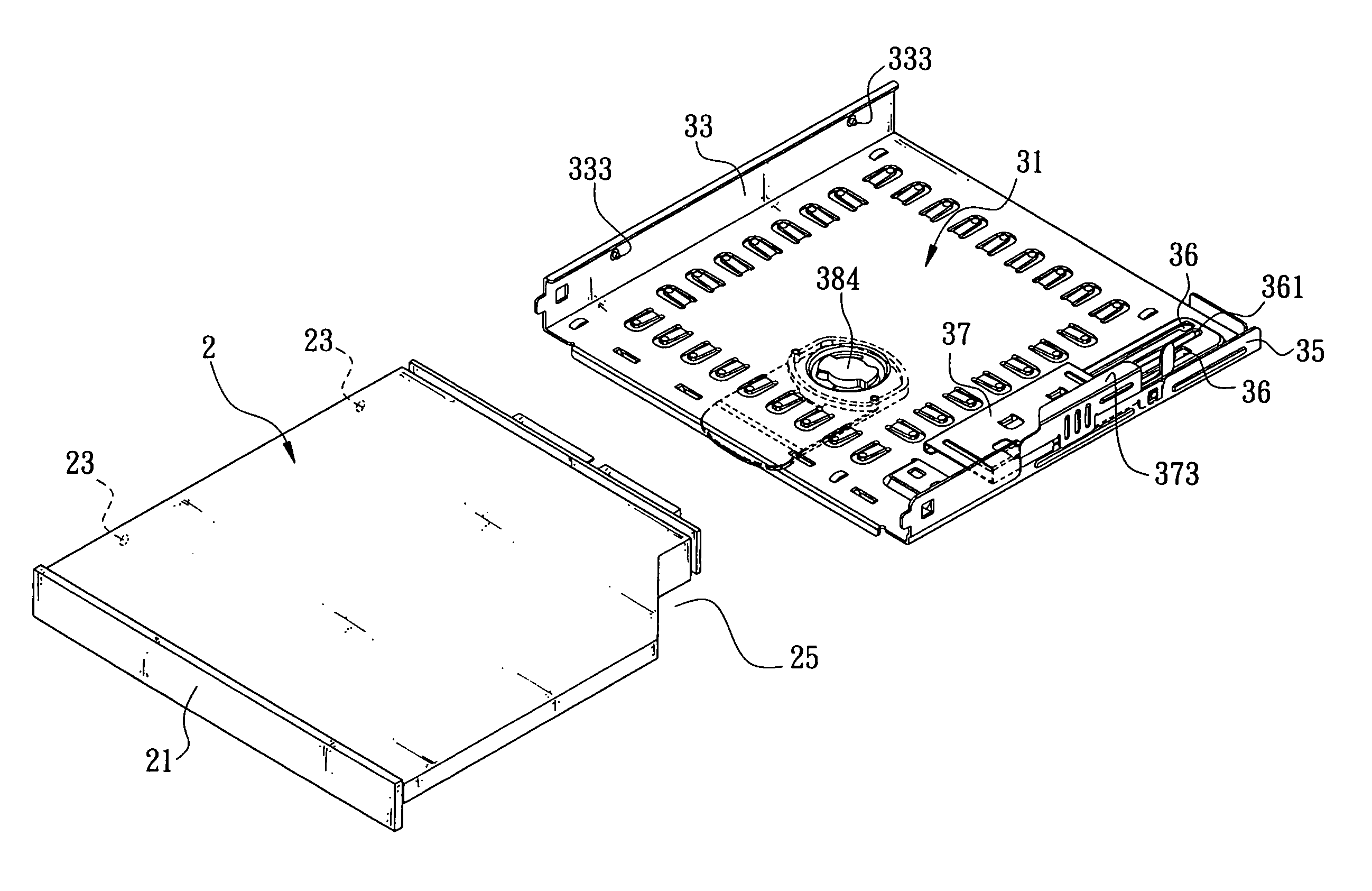
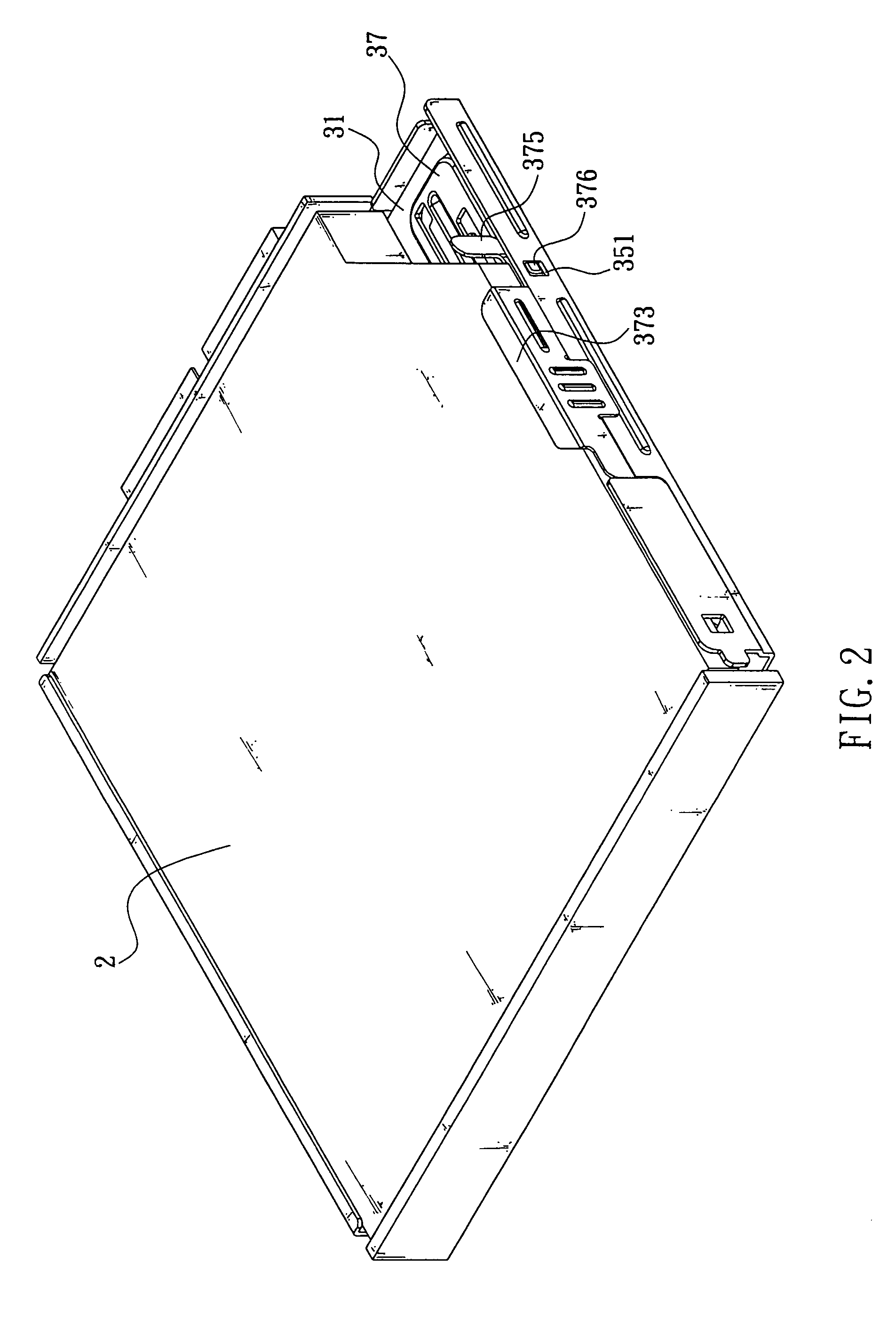
[0016]Referring to FIG. 2 and FIG. 3, the present invention is installed inside a cavity (not shown in FIG) of a computer and is composed of a frame 31, an inverted “L” shape sliding slot 33 is on one side of the frame 31, a wall 35 is on the edge of the other side thereof, referring to FIG. 3, FIG. 4 and FIG. 5, a sliding track is on the wall 35 closes to the frame 31; a pair of open slots 36 are on the sliding track, the pair of open slots 36 are parallel to each other, a rib 361 is between the open slots 36; a stopper 37 can move freely is on the open slot 36, a pair of hooks 371 (as shown in FIG. 6) are on the bottom of the stopper 37 to hook on the corresponding open slots 36 and make the stopper 37 move back and forward on the open slots 36; an inverted “L” shape standing stopper 373 is on one side of the wall 35 facing the stopper 37, a handle 375 is on the back of the standing stopper 373, a protruding bar 376 is on the handle 375, an opening 351 corresponding to the protrud...


PUM


Abstract

A fixing mechanism of an electronic device comprising a frame with an inverted “L” shape sliding slot on one side, a wall with a sliding track on one side is on the edge of the other side, a pair of open slots are on the sliding track, a stopper can move freely is on the open slots, an inverted “L” shape standing stopper is on one side of the wall facing the stopper, a handle is on the back of the standing stopper, a protruding bar is on the handle, an opening corresponding to the protruding bar is on the wall; when the stopper moves forward, the protruding bar wedges into the opening and fixes the stopper from moving. When an electronic device is installed on the frame, the electronic device is locked firmly onto the frame by the standing stopper pressing on both sides and can be moved out of the frame easily and rapidly.

Description

BACKGROUND OF THE INVENTION[0001]I. Field of the Invention[0002]This invention relates generally to a fixing mechanism of an electronic device and, more specifically, to a fixing mechanism of an electronic device that offers a simpler and faster method to take the electronic device out of a computer when the electronic device malfunctions.[0003]II. Description of the Prior Art[0004]Heretofore, it is known that a fixing mechanisms of a DVD drive, referring to FIG. 1, is to have a frame 10 of a DVD drive 2 installed onto a cavity of a computer; a plurality of through holes 13 are on the wall 11 of the frame 10, one screw 15 is on each through hole 13, same number of screw holes 16 corresponding to the through holes are on the DVD drive 2; when the DVD drive 2 is installed onto the frame 10, each screw 15 passes through the through hole 13 of the frame 10 and is fixed to the corresponding screw hole 16 on the DVD drive 2 to fix the DVD drive 2 on the cavity of the computer.[0005]The DV...

Claims


Application Information

Patent Timeline
Patent Type & Authority Patents(United States)
IPC IPC(8): H05K5/00G06F1/16G06F1/18
CPCG06F1/187G06F1/184
Inventor HSU, HSIN-AN
Owner FIRST INTERNATIONAL COMPUTER
Why Eureka
Try Eureka