Cutting fluid device for a spindle of a machine tool

a technology of cutting fluid and machine tool, which is applied in the direction of attachable milling devices, manufacturing tools, transportation and packaging, etc., can solve the problems of shortening the span of the cutting tool, and affecting the health of the user, so as to improve the responsiveness to ejecting start or stop instruction, prevent liquefaction of atomized cutting fluid, and facilitate production

Inactive Publication Date: 2006-05-23
HORKOS
View PDF19 Cites 67 Cited by
  • Summary
  • Abstract
  • Description
  • Claims
  • Application Information

AI Technical Summary

Benefits of technology

[0014]An atomized cutting fluid generator for generating atomized cutting fluid is provided in the cutting fluid passage on the spindle side. According to this, the atomized cutting fluid passage is shortened, thereby preventing liquefaction of the atomized cutting fluid and

Problems solved by technology

In this case, there happen many problems such as environmental pollution due to cutting fluid, a bad influence to human health, a big cost for waste oil disposal of the cutting fluid, shortening span of the cutting tool by supercooling the workpiece, and sliding wear of the cutting tool due to excessive cutting

Method used


Image

  • Cutting fluid device for a spindle of a machine tool
  • Cutting fluid device for a spindle of a machine tool
  • Cutting fluid device for a spindle of a machine tool

Examples


first embodiment

[0026]First of all, the invention will be explained.

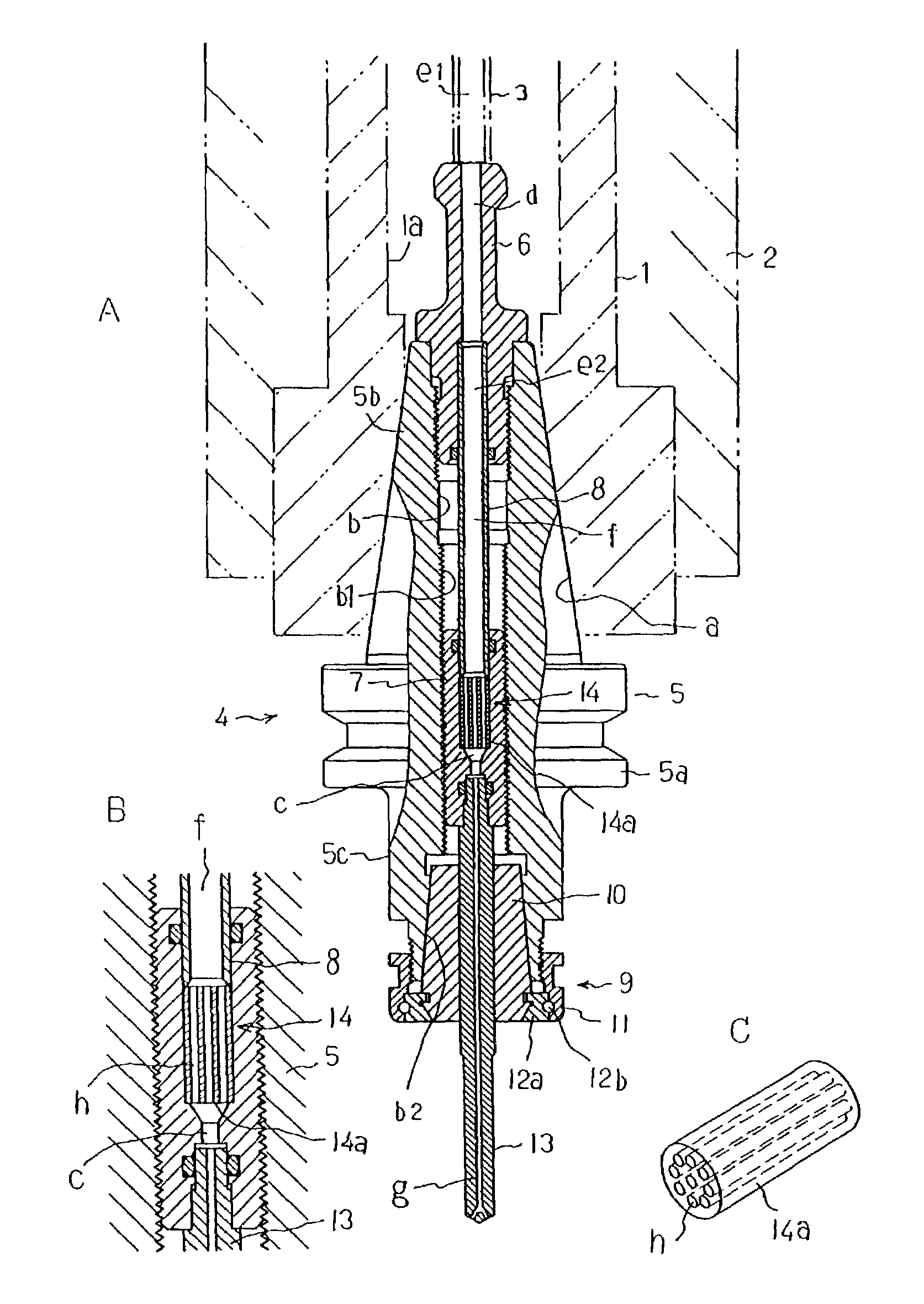
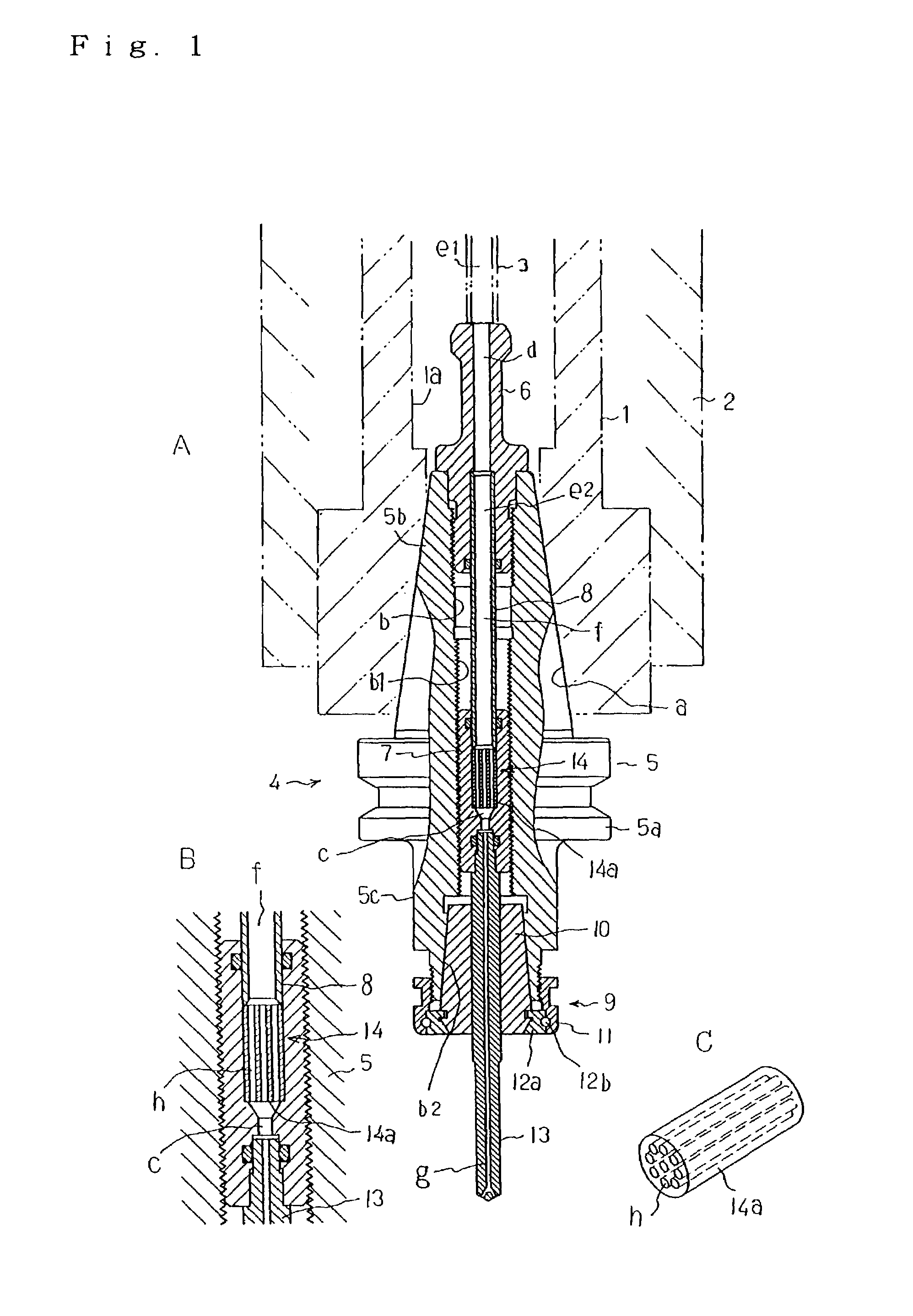
[0027]In FIG. 1, 1 is a bar spindle, which is supported to a spindle support frame 2 of a machine tool by not-illustrated bearings so as to freely rotate around the center of the spindle 1. The spindle 1 has a central hole 1a whose tip forms into a taper hole “a”. An inner pipe 3 is fixed at the center of the central hole 1a in one piece with the spindle 1.

[0028]Numeral 4 is a tool holder that is attached and detached by a tool exchange device. Here, the middle of a holder body 5 forms into a flange part 5a, a portion behind the flange 5a into a shank part 5b, and a portion in front thereof into a round bar-shape anterior overhang part 5c. Besides, the holder body 5 has an inner hole “b” to the center. A pull-stud 6 screws on the rear end of the inner hole “b”. A female screw b1 is formed to the comparatively long range of the anterior part thereof. The forefront part thereof forms into a taper hole b2. Here, an adjusting screw 7 h...

second embodiment

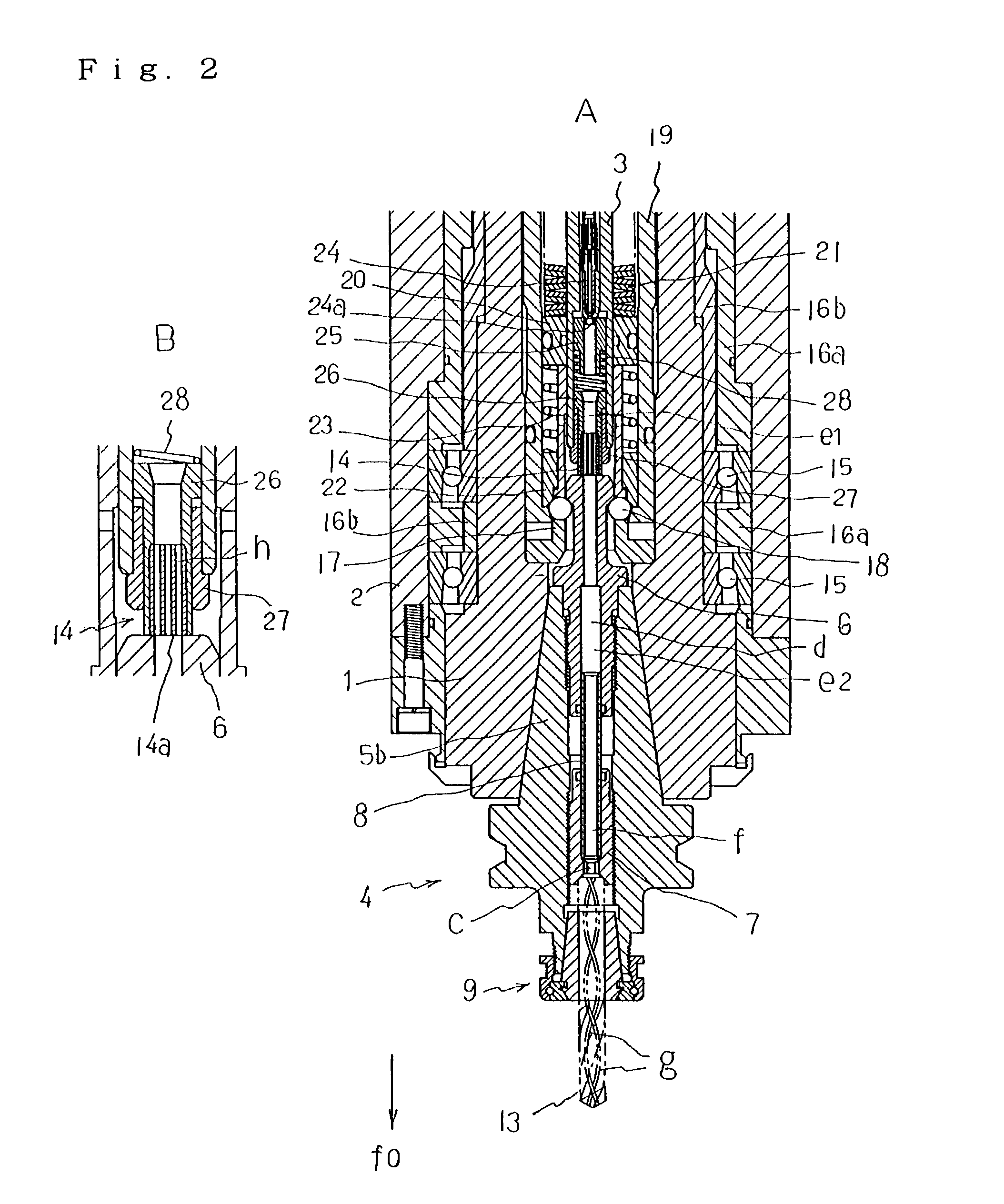
[0038]the invention will be explained. FIG. 2 is a sectional view from a side sight, which illustrates a spindle device of a machine tool regarding this embodiment.

[0039]In the figure, between a spindle 1 and a spindle support frame 2, are provided bearings 15, 15 for supporting the spindle 1 rotatively, and spacers 16a, 16a for regulating the relative position of the spindle 1, the spindle support frame 2 and the bearings 15, 15.

[0040]Numeral 17 is a canister inserted into the anterior part of the parallel part of the central hole 1a of the spindle 1, which has one or more through holes in a radial direction on the peripheral wall. A ball member 18 is guided inside each of the through holes movably in the radial direction of the peripheral wall. To the peripheral wall of the canister 17, is extrapolated a cylindrical clamp rod 19 guided to the central hole 1a of the spindle 1 movably in a longitudinal direction. When the clamp rod 19 moves to the front f0 to the spindle 1, the ball...

third embodiment

[0055]Next, the invention will be explained. FIG. 3 is a sectional view, which illustrates a spindle device of a machine tool concerning this embodiment.

[0056]As shown in the figure, a canister guide cylindrical member 29 is interiorly fitted close to the foremost parallel part of a central hole 1a of a spindle 1. And a clamp rod 30 is inserted into an inner hole of the guide cylindrical member 29 movably in a longitudinal direction. The clamp rod 30 has a central hole 30a. And the front of the clamp rod 30 forms a canister part 30b. One or more through holes in a radial direction of the spindle are provided in a peripheral wall of the front end of the canister part 30b. A ball member 18 is inserted into each of the through holes movably in the radial direction of the spindle.

[0057]A compressed disk spring group 21 is inserted behind the guide cylindrical member 29 inside the central hole 1a of the spindle 1. The spring group 21 presses the guide cylindrical member 29 to the front, ...


PUM

PropertyMeasurementUnit
Diameteraaaaaaaaaa
Diameteraaaaaaaaaa
Sizeaaaaaaaaaa

Abstract

A spindle device of a machine tool, which can prevent the liquefaction of atomized cutting fluid in atomized cutting fluid passage downstream of a straightening unit 14, enhance a responsiveness to an ejecting start or stop instruction, and prevent a waste of cutting fluid. The spindle device for a machine tool has atomized cutting liquid passage (e1, e2) each having a single-shape passage section and formed inside the device ranging from the spindle 1 to the tip end of a cutting tool 13 mounted thereto in one piece, and is operated so as to eject atomized cutting tool 13 via the atomized cutting fluid passages (e1, e2), wherein a straightening unit 14 formed with a plurality of small-diameter passages h are provided in the middle of the cutting liquid passages (e1, e2).

Description

FIELD OF THE INVENTION[0001]The present invention relates to a spindle device of a machine tool, which ejects atomized cutting fluid from the tip of a cutting tool.BACKGROUND OF THE INVENTION[0002]In machining due to a machine tool, much cutting fluid is supplied into a machining point to cool and lubricate a workpiece or a cutting tool, or to remove cutting chips. In this case, there happen many problems such as environmental pollution due to cutting fluid, a bad influence to human health, a big cost for waste oil disposal of the cutting fluid, shortening span of the cutting tool by supercooling the workpiece, and sliding wear of the cutting tool due to excessive cutting fluid during fine cutting machining. In addition, because much cutting fluid adheres to the cutting chips during machining, the adhered cutting fluid must be removed from the cutting chips in treating or recycling.[0003]To settle these problems, recently, a machine tool that carries out so-called dry cutting has ap...

Claims


Application Information

Patent Timeline
IPC IPC(8): B23Q11/10
CPCB23Q11/10Y10T408/44Y10T409/304032Y10T408/45Y10T409/303976Y10T409/309352Y10T408/455B23Q11/1023
Inventor SUGATA, SHINSUKEMAKIYAMA, TADASHI
Owner HORKOS
Why Eureka
Try Eureka