
Dental implement for tooth restorations

Active Publication Date: 2006-07-18
ANDERSON ROBERT
View PDF12 Cites 21 Cited by
  • Summary
  • Abstract
  • Description
  • Claims
  • Application Information

AI Technical Summary

Benefits of technology

[0017]From the foregoing, it can be appreciated that the dental implement of the present invention provides a retaining device that generates a greater se

Problems solved by technology

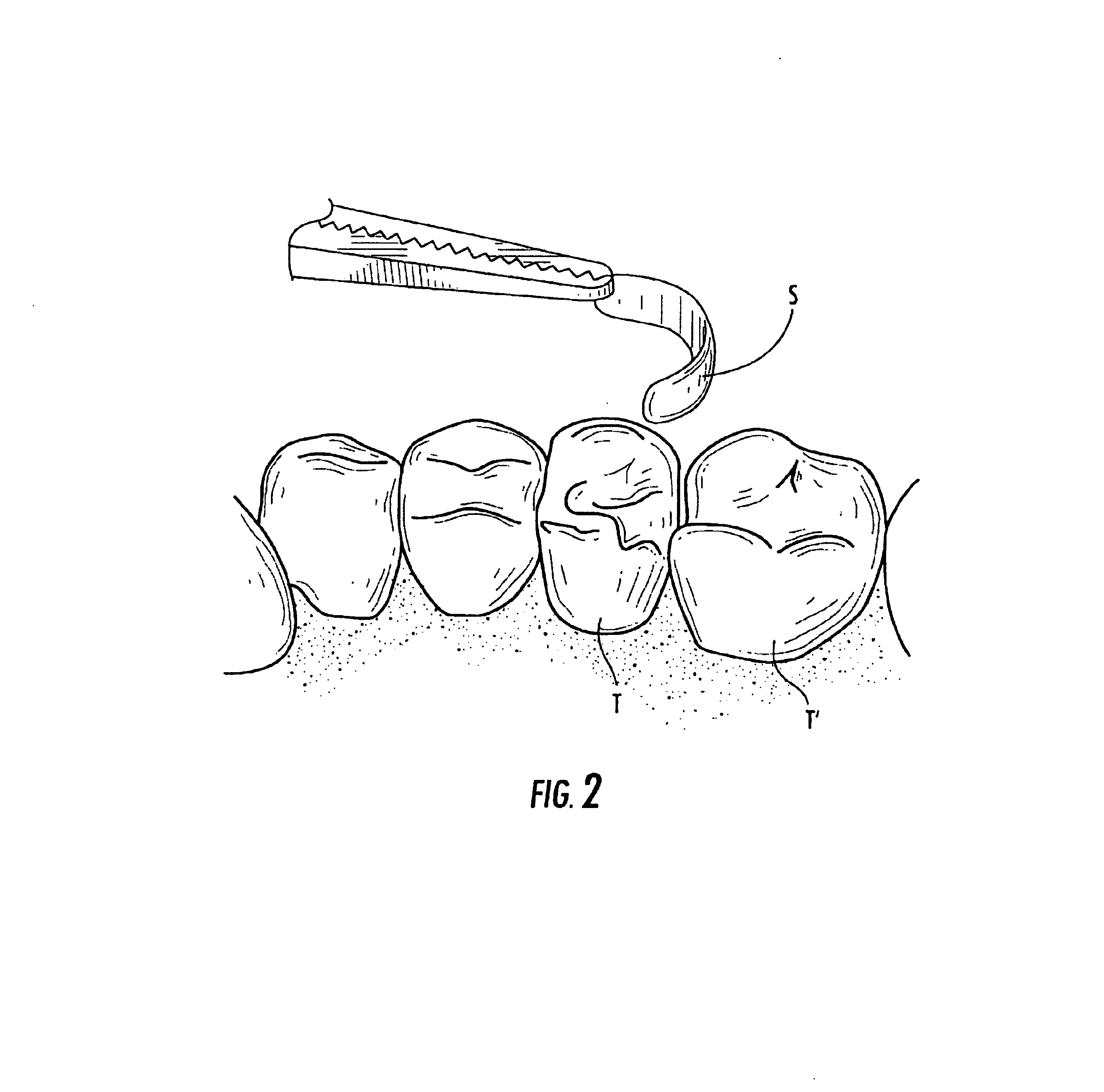
When the decayed portion is located near its interproximal area between an adjacent tooth, the tooth structure is usually insufficient to provide support to the filling material during the filling process.
However, when the tines are moved between their initial, unloaded state to their separated, loaded state, over time, it has been found that these rings undergo significant and appreciable plastic deformation and, consequently, lose their resilience and strength.
Therefore, over time, the rings lose their ability to generate a sufficient force to properly hold the band in place against the tooth and, further, to generate sufficient force to separate the teeth.

Method used


Image

  • Dental implement for tooth restorations
  • Dental implement for tooth restorations
  • Dental implement for tooth restorations

Examples


Embodiment Construction

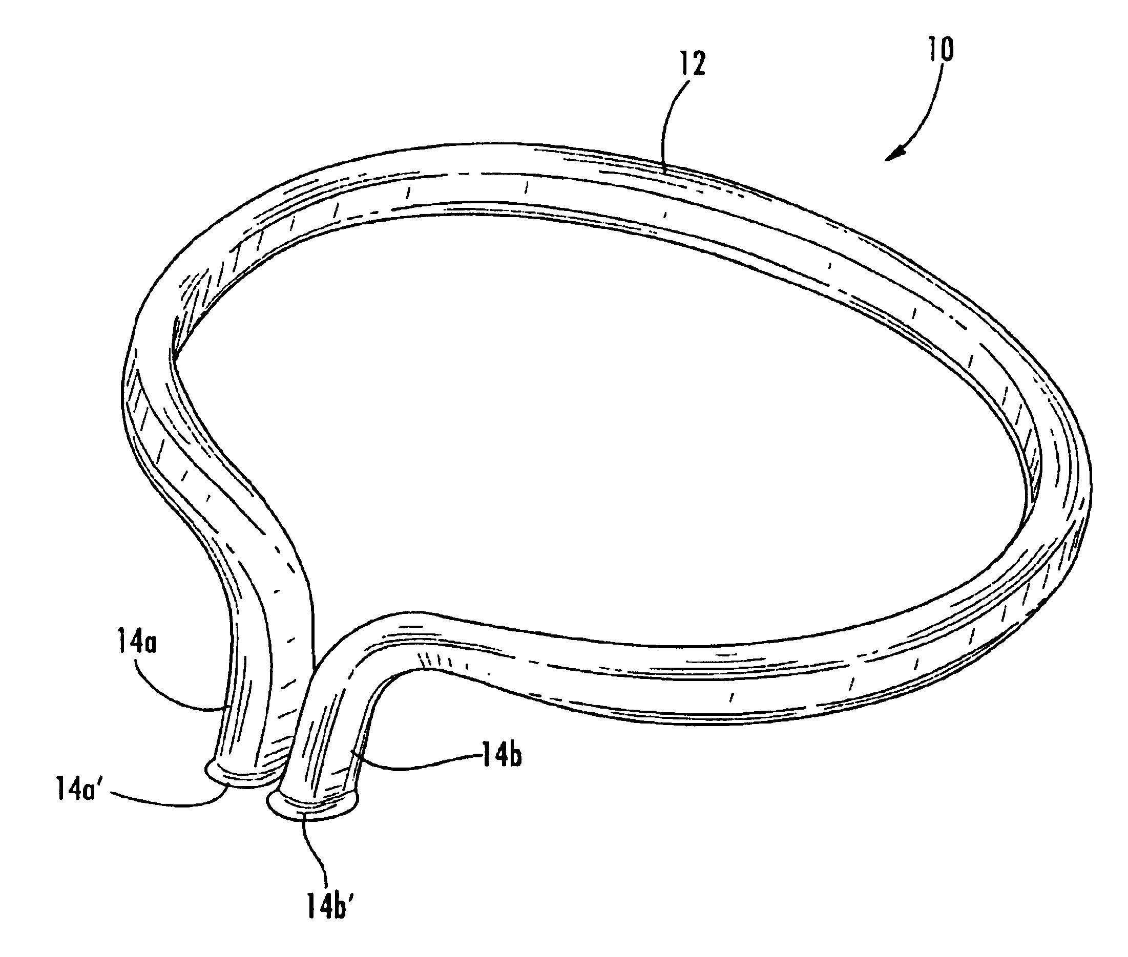
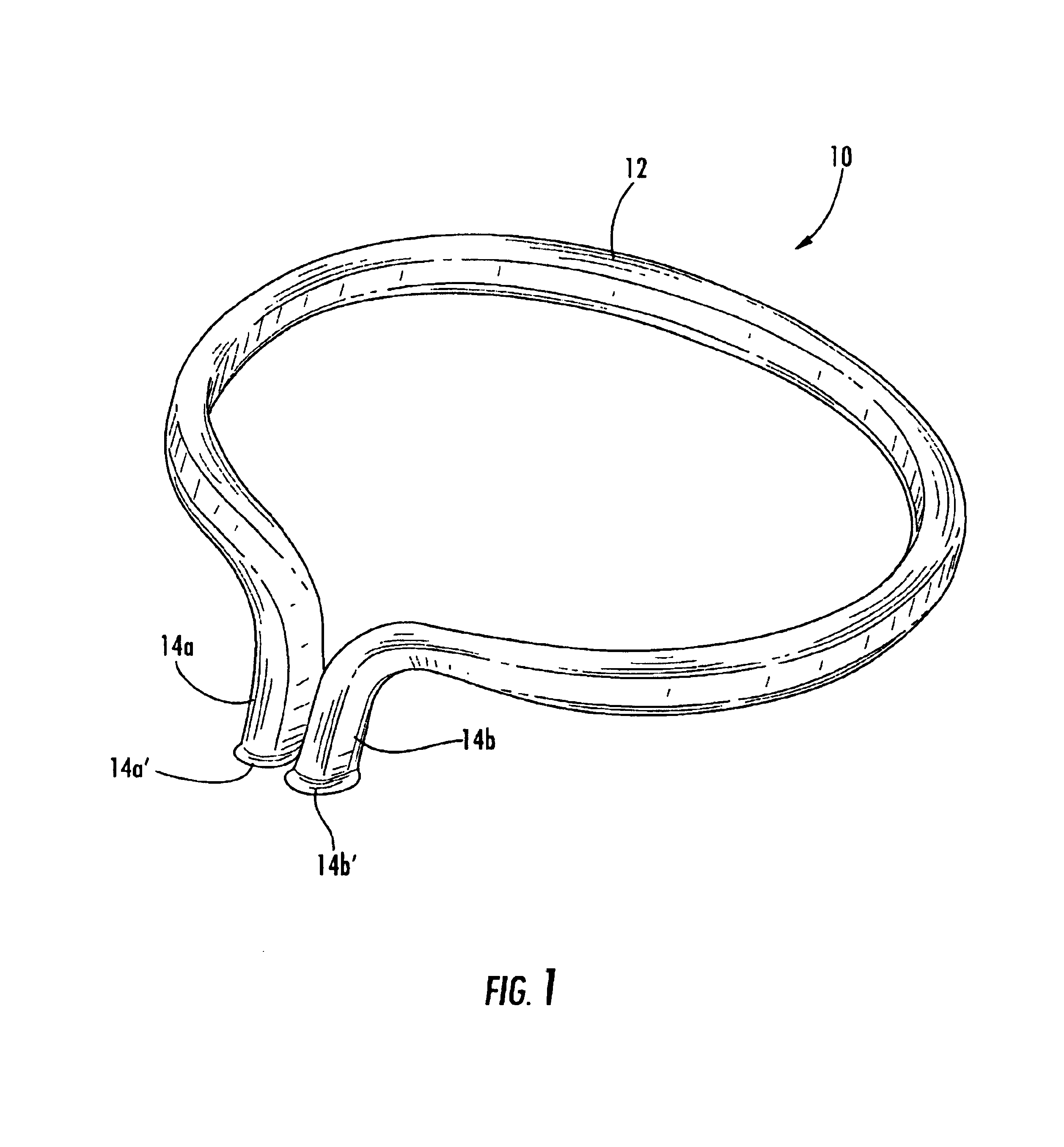
[0030]Referring to FIG. 1, the numeral 10 generally designates a dental implement of the present invention. Dental implement 10 comprises a retaining device for retaining a band or matrix against a tooth undergoing repair. Dental implement 10 includes generally ring-shaped portion 12 and a pair of downwardly depending prongs or tines 14a and 14b. As will be more fully described below, tines 14a and 14b are formed such that at least a portion of the tines touch when the implement is in its initial uninstalled state. As a result, the amount of force needed to move or separate the tines from their initial uninstalled state to an installed state is greater than conventional open-ended ring-type implements. Further, implement 10 retains its resiliency so that the implement can be reused and reinserted without losing its resiliency and strength needed to separate the teeth.

[0031]Referring to FIGS. 2-5, when a mesial or distal interproximal area of a tooth T′ needs to be repaired or restor...


PUM


Abstract

A dental implement includes a wire member that forms a generally ring-shaped portion and first and second ends, which depend from the ring-shaped portion. The ring-shaped portion lies in a plane, with the first and second ends depending from the generally ring-shaped portion in a direction generally orthogonal to the plane. At least a portion of the first end touches at least a portion of the second end when in an initial resting state, wherein the first and second ends generate an inward force towards each other when separated.

Description

TECHNICAL FIELD AND BACKGROUND OF THE INVENTION[0001]This application incorporates by reference in its entirety pending U.S. provisional Pat. application entitled DENTAL IMPLEMENT FOR TOOTH RESTORATIONS, Ser. No. 60 / 355,578, filed Feb. 7, 2002.[0002]The present application relates to a dental implement and, more particularly, to a retaining device, which is used to separate teeth and, further, to hold a contour band in place around a tooth when a cavity in the tooth is to be filled.[0003]When a tooth includes a decayed portion, the decayed portion is excavated and then filled. When the decayed portion is located near its interproximal area between an adjacent tooth, the tooth structure is usually insufficient to provide support to the filling material during the filling process. In order to retain the filling material in the cavity while it hardens, a tooth reconstruction element (typically a thin band, which is usually made of stainless steel or the like) is positioned about the to...

Claims


Application Information

Patent Timeline
IPC IPC(8): A61C5/12
CPCA61C5/125A61C5/122A61C5/82A61C5/85
Inventor ANDERSON, ROBERT
Owner ANDERSON ROBERT
Learn More