Biopsy marker delivery system

a delivery system and biopsy technology, applied in medical science, surgery, vaccination/ovulation diagnostics, etc., can solve the problems of prolonging the duration of the procedure, unneeded additional discomfort for patients, and inability to remove a sufficient amount of lesion from the initial biopsy, so as to prevent further distal movement of the rod

a delivery system and biopsy technology, applied in medical science, surgery, vaccination/ovulation diagnostics, etc., can solve the problems of prolonging the duration of the procedure, unneeded additional discomfort for patients, and inability to remove a sufficient amount of lesion from the initial biopsy, so as to prevent further distal movement of the rod

US7083576B2Inactive Publication Date: 2006-08-01DEVICOR MEDICAL PROD

Image

  • Biopsy marker delivery system
  • Biopsy marker delivery system
  • Biopsy marker delivery system

Examples


Embodiment Construction

[0038]The following discussion of the variations of the invention and the reference to the attached drawings are for explanatory purposes and do not exhaustively represent the possible combinations and variations of the invention. Those skilled in the art will readily appreciate that many variations may be derived using the following description. The following examples are intended to convey certain principles of the invention. These examples are not intended to limit the scope of the claims to any particular example. It is understood that the claims are to be given their broadest reasonable interpretation in view of the description herein, any prior art, and the knowledge of those of ordinary skill in the field. Furthermore, it is understood that the invention is not limited to the markers described herein. Instead, the invention may be used with any type of biopsy marker or tissue marker.

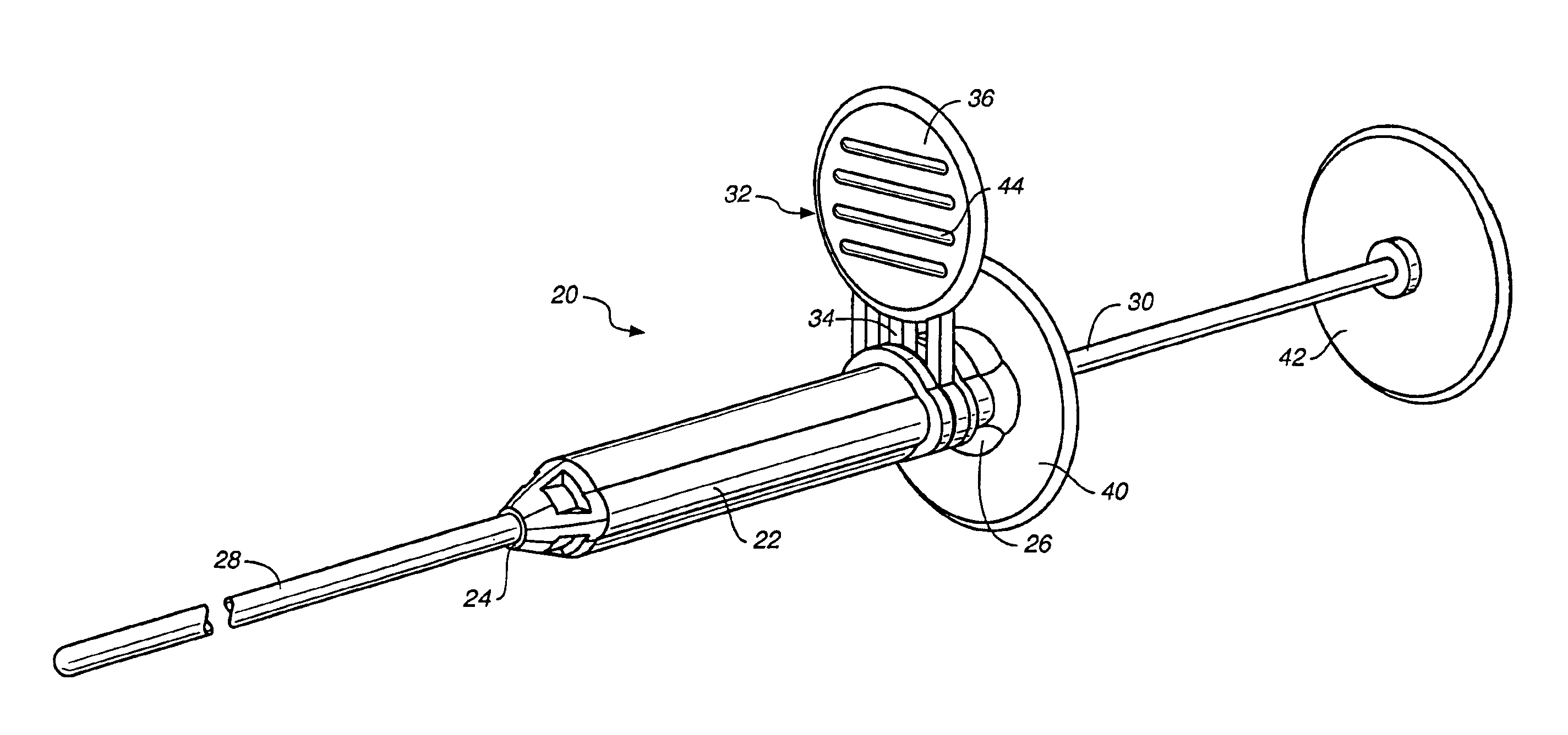
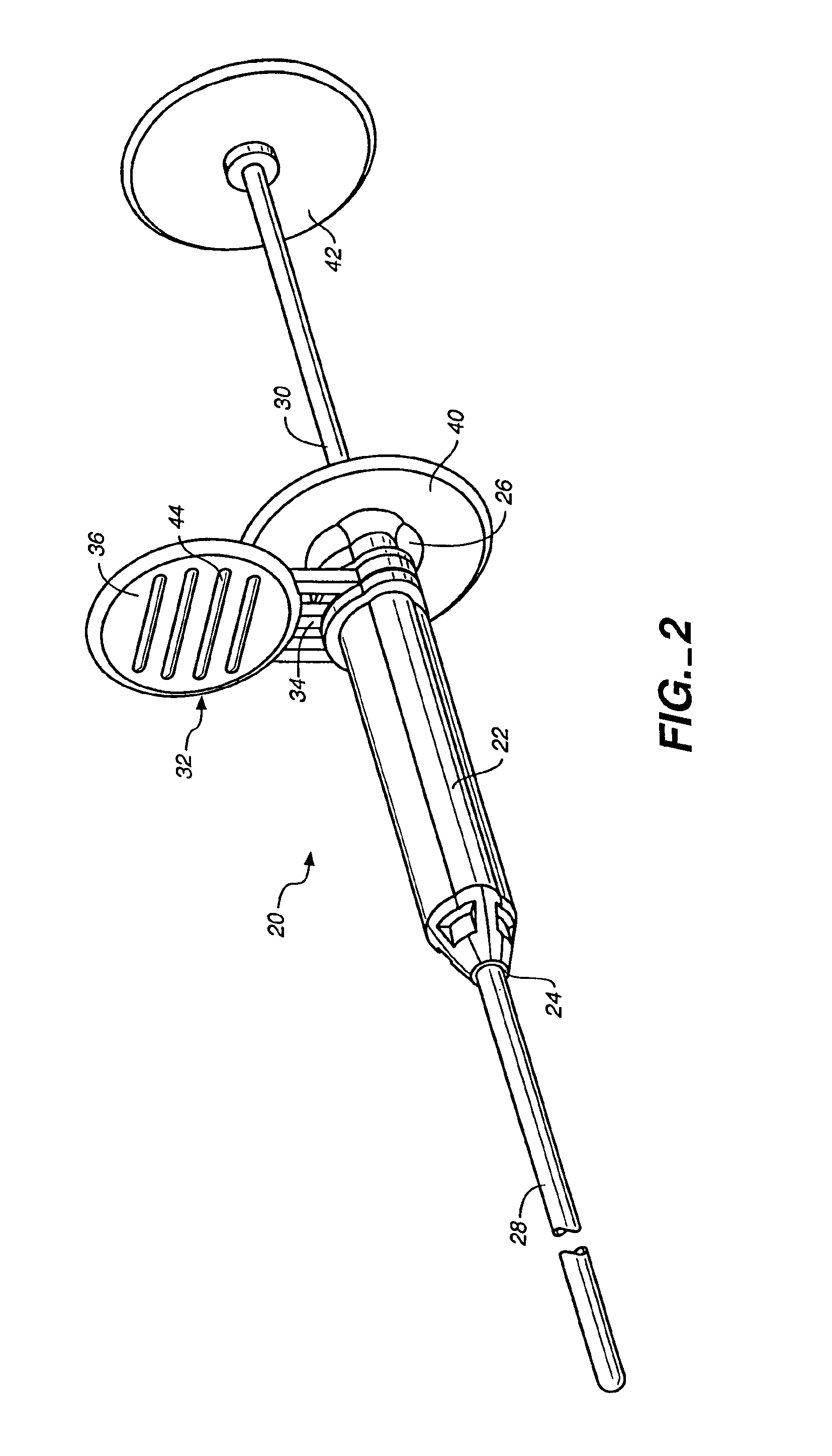
[0039]FIG. 2 illustrates a perspective view of a variation of a biopsy marker delivery device ...


PUM


Abstract

An apparatus for delivering subcutaneous cavity marking devices. More particularly, the delivery devices may be used with biopsy systems permitting efficient placement of a biopsy marker within a cavity. The device may include an intermediate member which assists in deployment of the marking device. The devices may also include a deployment lock to prevent premature deployment of a biopsy marker. The invention may further include the capability to match an orientation of a biopsy probe which has been rotated upon procurement of a biopsy sample.

Description

[0001]This application is a continuation of U.S. application Ser. No. 09 / 954,792, filed Sep. 10, 2001, now U.S. Pat. No. 6,605,047, the contents of which is hereby incorporated by reference into the present disclosure.FIELD OF THE INVENTION[0002]This invention is directed to delivery devices for delivering subcutaneous cavity marking devices. More particularly, the delivery device may be used with biopsy systems permitting efficient placement of a biopsy marker within a cavity. The device may include an intermediate member which assists in deployment of the marking device. The device may also include a deployment lock to prevent premature deployment of a biopsy marker. The invention may further include the capability to match an orientation of a biopsy probe that has been rotated upon procurement of a biopsy sample.BACKGROUND OF THE INVENTION[0003]Over 1.1 million breast biopsies are performed each year in the United States alone. Of these, about 80% of the lesions excised during bi...

Claims


Application Information

Patent Timeline
01 Aug 2006
Publication
US7083576B2
IPC
A61B10/00; A61B10/02; A61B17/00; A61B19/00
CPC
A61B10/0275; A61B19/54; A61B10/0283; A61B2019/5487; A61B2019/304; A61B2019/308; A61B2017/00539; A61B2090/038
Inventors
ZARINS, SASCHA; KIM, STEVEN