Multi-photon endoscopic imaging system

a multi-photon and endoscopic technology, applied in the field of multi-photon imaging systems, can solve the problems of lowering peak intensities and low absorption rates of multi-photons, and achieve the effect of widening the optical cor

Active Publication Date: 2006-08-15
LUCENT TECH INC
View PDF18 Cites 134 Cited by
  • Summary
  • Abstract
  • Description
  • Claims
  • Application Information

AI Technical Summary

Benefits of technology

[0013]In one aspect, the invention features an imaging system that includes a pulsed laser, a pre-compensator, a transmission optical fiber, and a GRIN lens with a wider optical core than the transmission optical fiber. The pre-compensator is configured to receive optical pulses produced by the pulsed laser and to chirp the optical pulses to pre-compensate for chromatic dispersion. The transmission optical fiber is configured to receive the chirped optical pulses from the pre-compensator. The GRIN lens is configured to receive the optical pulses transported by the transmission optical fiber and to substantially temporally narrow the optical pulses received from the transmission optical fiber.

Problems solved by technology

Unfortunately, rates for multi-photon absorptions are low unless illumination has a high peak intensity.
Unfortunately, transmission through optical fibers often broadens optical pulses thereby lowering peak intensities.
Unfortunately, a multi-modal fiber can also introduce pulse broadening due to modal dispersion.

Method used


Image

  • Multi-photon endoscopic imaging system
  • Multi-photon endoscopic imaging system
  • Multi-photon endoscopic imaging system

Examples


Embodiment Construction

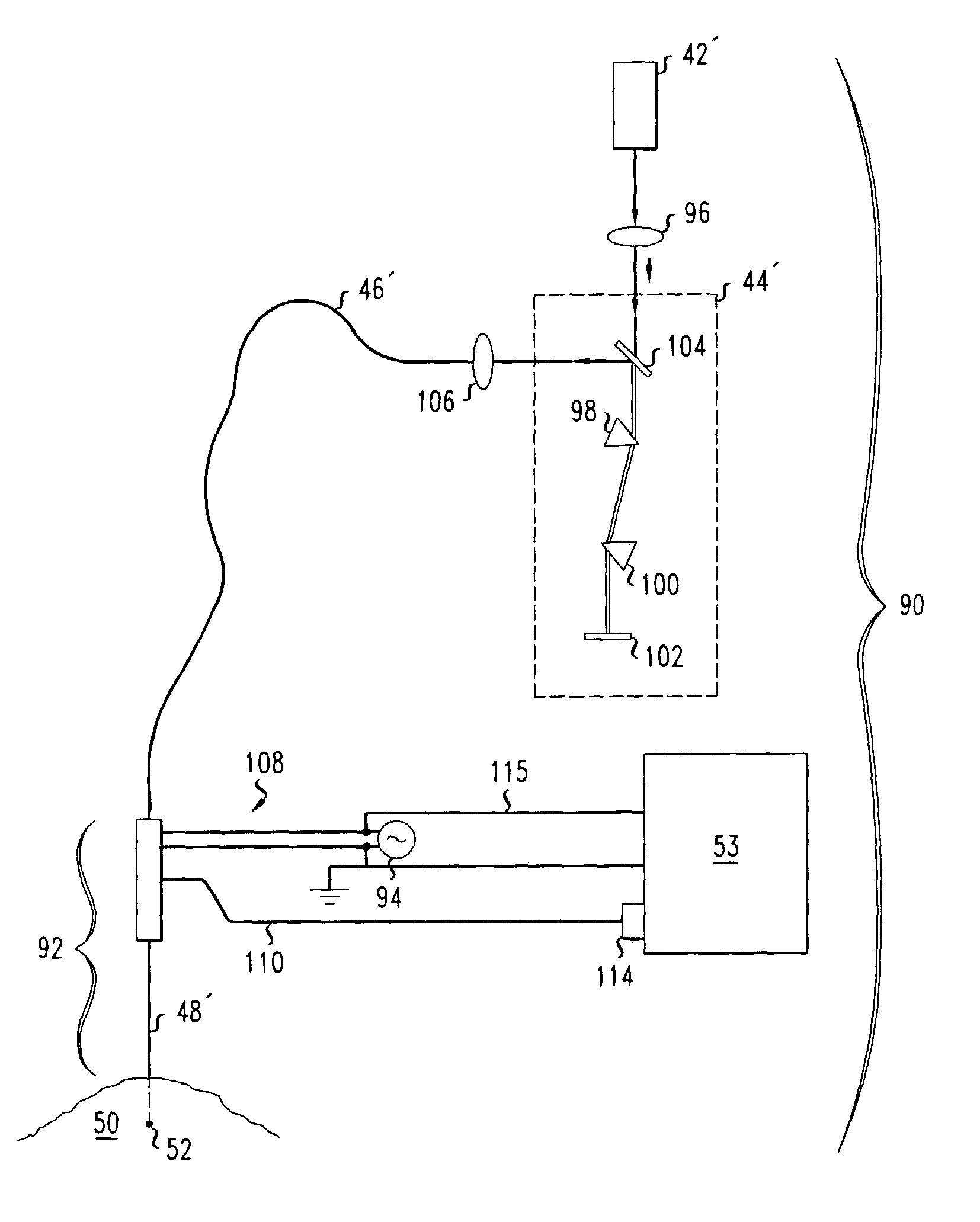
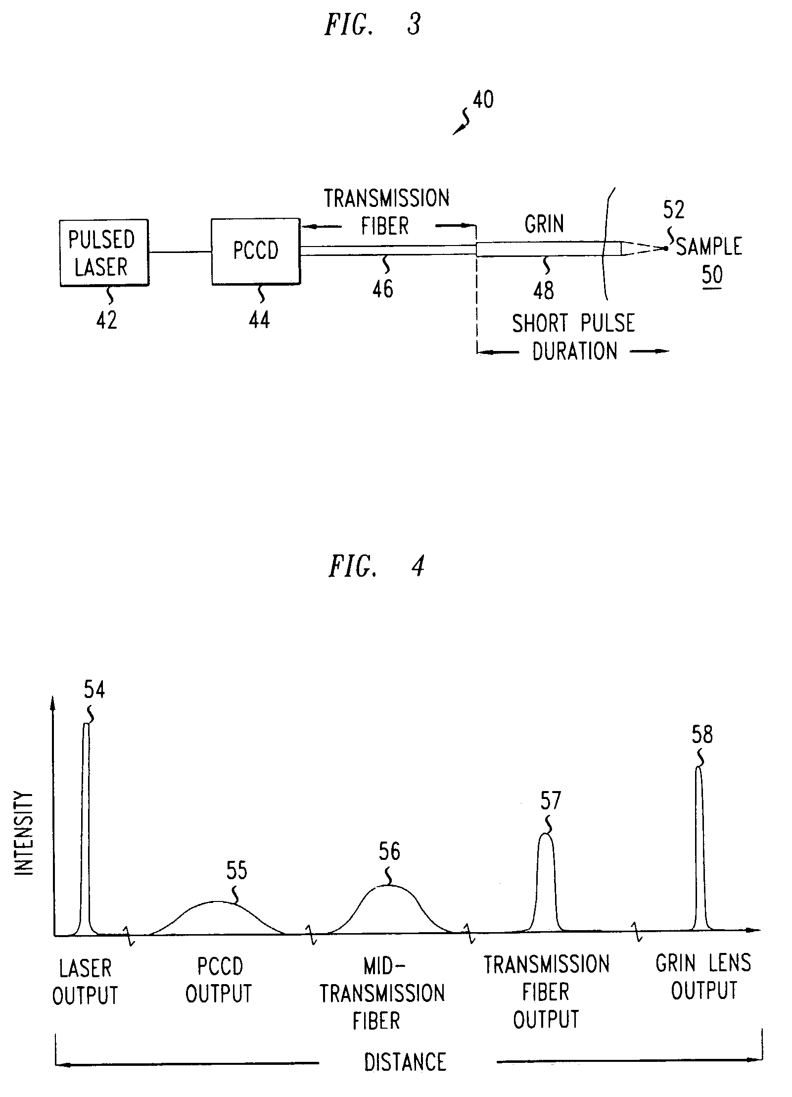
[0028]FIG. 3 schematically illustrates an illumination portion 40 of a scanning multi-photon imaging system. The illumination portion 40 includes a pulsed laser 42, a pre-compensator for chromatic dispersion (PCCD) 44, a transmission optical fiber 46, and a graded index (GRIN) lens 48. The pulsed laser 42 produces optical pulses with short temporal widths and high peak intensities. The high peak intensities are suitable for illumination light in multi-photon imaging. The PCCD 44 chirps the optical pulses from the laser 42 in a manner that pre-compensates for chromatic dispersion in both the transmission optical fiber 46 and the GRIN lens 48. The transmission optical fiber 46 delivers the chirped optical pulses to the GRIN lens 48 with low or no modal dispersion. Exemplary transmission optical fibers include single mode optical fibers (SMFs), GRIN optical fibers, and serial combinations of GRIN optical fibers and SMFs. The GRIN lens 48 has an optical core with a larger diameter than ...


PUM

PropertyMeasurementUnit
wavelengthsaaaaaaaaaa
core diameteraaaaaaaaaa

Abstract

An imaging system includes a pulsed laser, a pre-compensator for chromatic dispersion, a transmission optical fiber, and a GRIN lens. The pre-compensator chirps optical pulses received from the laser. The transmission optical fiber transports the chirped optical pulses from the pre-compensator. The GRIN lens receives the transported optical pulses from the transmission optical fiber. The GRIN lens has a wider optical core than the transmission optical fiber and substantially narrows the transported optical pulses received from the transmission optical fiber.

Description

BACKGROUND[0001]1. Field of the Invention[0002]The invention relates generally to multi-photon imaging systems.[0003]2. Discussion of the Related Art[0004]In multi-photon imaging, molecules are excited via absorptions of two or more photons and imaged via light emitted during molecular de-excitations. The imaging light has a different wavelength than the exciting light and is emitted by selected molecular species, e.g., dye molecules. For these reasons, multi-photon imaging can produce tissue-selective images, e.g., of blood or neural tissue. In medical diagnostics, tissue-selective images are useful for in vivo analysis. Unfortunately, rates for multi-photon absorptions are low unless illumination has a high peak intensity. For example, rates for two-photon absorption events grow as a square of the illumination intensity.[0005]For imaging applications, acceptable multi-photon absorption rates usually require intense illumination. Some imaging systems use very short optical pulses t...

Claims


Application Information

Patent Timeline
Patent Type & Authority Patents(United States)
IPC IPC(8): G01N21/64A61B5/00G02B23/26
CPCA61B5/0084G02B23/26G01N21/6458A61B5/0086G01N2021/6415
Inventor SCHNITZER, MARK J
Owner LUCENT TECH INC
Why Eureka
Try Eureka