Toner transfer technique
a technology of electrophotographic printer and transfer technique, which is applied in the direction of electrographic process apparatus, instruments, optics, etc., can solve the problems of inability to direct measure q/m, inability to accurately detect the q/m of the toner layer, and small defects in the previously deposited toner layer, etc., to achieve useful, reduce back-transfer, and reduce the effect of back-transfer
- Summary
- Abstract
- Description
- Claims
- Application Information
AI Technical Summary
Benefits of technology
Problems solved by technology
Method used
Image
Examples
example 1
Relation Between Magnitude of Pre-exposure Surface Potential and Charge-to-mass Ratio (q / m)
[0065]FIG. 5 relates to a module similar to the module of FIG. 2, and shows an exemplary experimentally determined linear relation between magnitude of pre-exposure surface potential measured on the photoconductive image-recording roller and charge-to-mass ratio (q / m) of toner particles used in the development station of the module. The magnitudes of pre-exposure surface potential, V0, were established using a process control system similar to that described for embodiment 200, i.e., in which a toner control patch was formed on a transport web. The toner control patch was formed for different developers for which the q / m was measured off-line. The process control system caused adjustments of operational control parameters for establishing the V0 magnitudes such that a same maximum optical density of the toner control patch was produced for each q / m value tested.
[0066]The photoconductive image-...
example 2
Experimentally-determined Values of Parameters Relating to FIG. 4
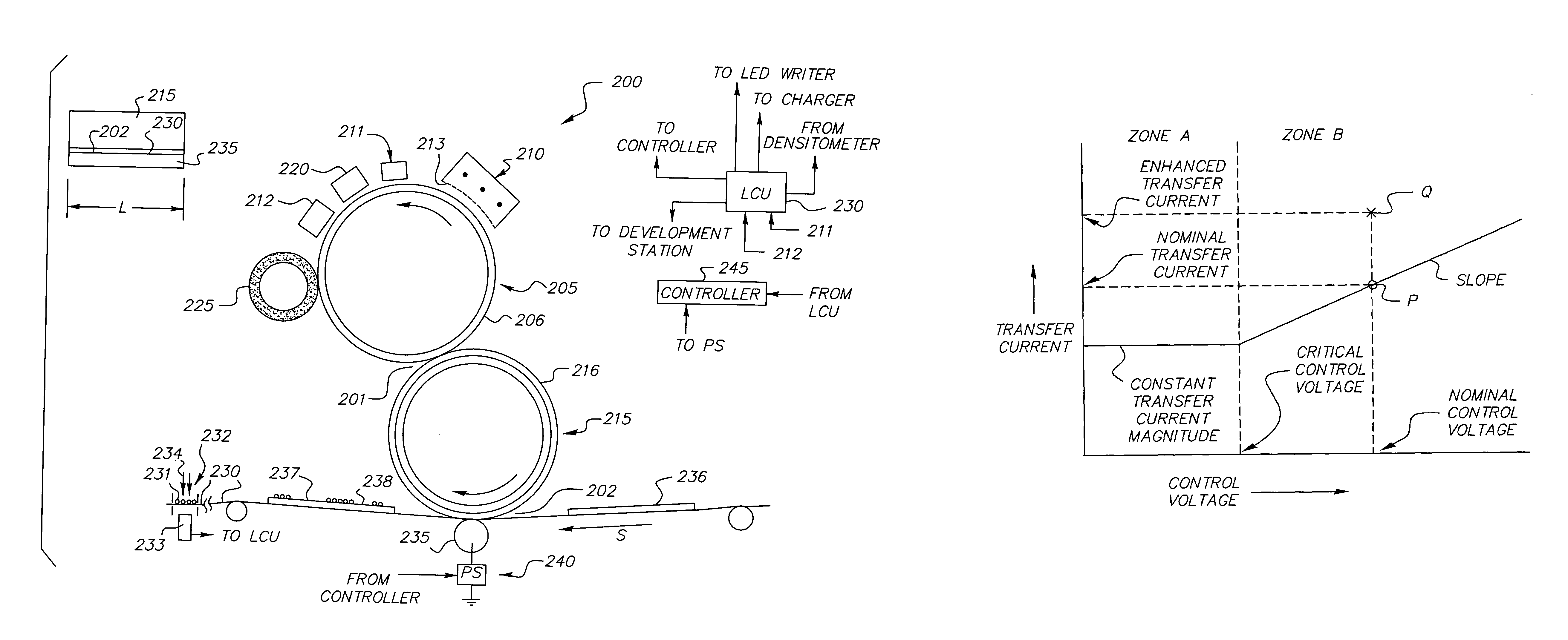
[0068]Experiments were carried out to measure values of the three parameters defining the functional relationship of FIG. 4, namely, the minimum practical constant transfer current magnitude in Zone A, the critical control voltage dividing Zones A and B, and the minimum practical slope in zone B. The results are shown in FIG. 6. The same module and similar developers were used as for Example 1. A process speed S of 300 mm / sec and a nip length L of 360 mm were used. The intermediate transfer roller had a doped polyurethane blanket coated with a thin ceramer layer.
[0069]In FIG. 6, control voltage parameter magnitude is magnitude of V0, ranging between 300 volts and 800 volts. The critical control voltage magnitude is 500 volts. Thus below 500 volts, a constant transfer current of about 18 microamperes is used. Above 500 volts, the slope of the experimentally determined line is 0.050 microampere / volt.
[0070]It may be noted...
PUM
 Abstract
Description
Claims
Application Information
 - R&D
- Intellectual Property
- Life Sciences
- Materials
- Tech Scout
- Unparalleled Data Quality
- Higher Quality Content
- 60% Fewer Hallucinations
Browse by: Latest US Patents, China's latest patents, Technical Efficacy Thesaurus, Application Domain, Technology Topic, Popular Technical Reports.
© 2025 PatSnap. All rights reserved.Legal|Privacy policy|Modern Slavery Act Transparency Statement|Sitemap|About US| Contact US: help@patsnap.com


