Toner transfer technique

a technology of electrophotographic printer and transfer technique, which is applied in the direction of electrographic process apparatus, instruments, optics, etc., can solve the problems of inability to direct measure q/m, inability to accurately detect the q/m of the toner layer, and small defects in the previously deposited toner layer, etc., to achieve useful, reduce back-transfer, and reduce the effect of back-transfer

Inactive Publication Date: 2005-11-03
EASTMAN KODAK CO
View PDF10 Cites 13 Cited by
  • Summary
  • Abstract
  • Description
  • Claims
  • Application Information

AI Technical Summary

Benefits of technology

[0016] This invention relates to a module, included in a modular electrophotographic printer in which a plurality of toner-image-forming modules are in tandem arrangement, which module is for making toner images by a method in which transfer current for electrostatic transfer of the toner images to receiver members in a transfer station is adjusted so as to produce output image density substantially independent of the charge-to-mass ratio (q/m) of the toner particles used in the module. An ob

Problems solved by technology

When the current-controlled mode of transfer operates in a particular module with at least two previously transferred toner layers already stacked on the receiver member from prior modules, the inventors have noted that a mottle defect can occur in the previously deposited toner layer farthest away from the surface of the receiver member.
However, in relatively large areas in which no toner particles are to be transferred, e.g., in the red area of this example, breakdown currents

Method used


Image

  • Toner transfer technique
  • Toner transfer technique
  • Toner transfer technique

Examples


example 1

Relation Between Magnitude of Pre-exposure Surface Potential and Charge-to-mass Ratio (g / m)

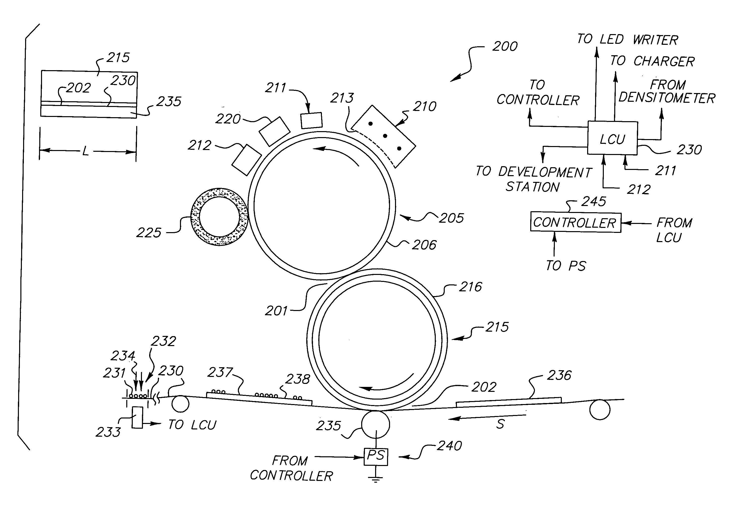
[0064]FIG. 5 relates to a module similar to the module of FIG. 2, and shows an exemplary experimentally determined linear relation between magnitude of pre-exposure surface potential measured on the photoconductive image-recording roller and charge-to-mass ratio (q / m) of toner particles used in the development station of the module. The magnitudes of pre-exposure surface potential, V0, were established using a process control system similar to that described for embodiment 200, i.e., in which a toner control patch was formed on a transport web. The toner control patch was formed for different developers for which the q / m was measured off-line. The process control system caused adjustments of operational control parameters for establishing the V0 magnitudes such that a same maximum optical density of the toner control patch was produced for each q / m value tested.

[0065] The photoconductive ima...

example 2

Experimentally-determined Values of Parameters Relating to FIG. 4

[0067] Experiments were carried out to measure values of the three parameters defining the functional relationship of FIG. 4, namely, the minimum practical constant transfer current magnitude in Zone A, the critical control voltage dividing Zones A and B, and the minimum practical slope in zone B. The results are shown in FIG. 6. The same module and similar developers were used as for Example 1. A process speed S of 300 mm / sec and a nip length L of 360 mm were used. The intermediate transfer roller had a doped polyurethane blanket coated with a thin ceramer layer.

[0068] In FIG. 6, control voltage parameter magnitude is magnitude of V0, ranging between 300 volts and 800 volts. The critical control voltage magnitude is 500 volts. Thus below 500 volts, a constant transfer current of about 18 microamperes is used. Above 500 volts, the slope of the experimentally determined line is 0.050 microampere / volt.

[0069] It may be ...


PUM


Abstract

A module, included in an electrophotographic printer, for making toner images by a method in which transfer current for electrostatic transfer of toner images to receiver members is adjusted to compensate for ambient variations of toner charge-to-mass ratio (q/m). A predetermined functional relationship between transfer current and a control voltage parameter is utilized. Magnitudes of the control voltage parameter are derived from voltage measurements relating to creation of toner control patches on a photoconductive image-recording member included in a modular electrophotographic printer. Control voltage magnitude is linearly dependent on q/m. The functional relationship, which is characterized by three experimentally determined parameters, is co-optimized for providing efficient transfer of toner images and for minimizing back-transfer of toner away from a receiver member in a transfer station included in the module.

Description

FIELD OF THE INVENTION [0001] The invention relates to electrostatic transfer in an electrophotographic printer, and in particular to apparatus and method for constant-current transfer of toner images. BACKGROUND OF THE INVENTION [0002] In an electrophotographic modular printing machine of known type, such as for example a NexPress 2100 printer manufactured by NexPress Solutions, Inc., of Rochester, N.Y., color toner images are made sequentially in a plurality of tandemly arranged color imaging modules, and the toner images are successively electrostatically transferred to a receiver sheet adhered to a transport web moved through the modules. Commercial machines of this type typically employ intermediate transfer members in the respective modules, e.g., for the transfer to the receiver member of individual color separation toner images. In a transfer station included in each module of a NexPress 2100 printer, a current-controlled transfer mode is used to transfer a respective color ...

Claims


Application Information

Patent Timeline
IPC IPC(8): G03G15/00G03G15/16
CPCG03G15/1675G03G15/5058G03G15/5037G03G2215/00033
Inventor RAKOV, DAVID M.WRIGHT, GRAHAM S.SHUSTER, FRANK A.
Owner EASTMAN KODAK CO
Why Eureka
Try Eureka