Deformable translatable seat for reducing stress on ceramic penetrators

a penetrator and translatable seat technology, applied in the field of electric power feedthrough, can solve the problems of reducing the stress or strain of the penetrator, the inability of the connection or penetrator to be isolated from the pumping pressure, and the extreme environment of the connector or penetrator, so as to reduce or eliminate the concentration of bearing stress and relieve shearing stress

Active Publication Date: 2019-04-02
TELEDYNE INSTR INC
View PDF48 Cites 0 Cited by
  • Summary
  • Abstract
  • Description
  • Claims
  • Application Information

AI Technical Summary

Benefits of technology

[0009]The present invention provides a system for providing a seal for an electrical penetrator in a subsea environment. More specifically, the present invention provides a deformable translatable seat in an oversized annular pocket that prevents the transfer of shear forces from a shell or fixture to a ceramic electrical penetrator or pin. The present invention provides a relatively soft metal annular seat that mates with and conforms to the profile of the shoulder of a mating electrical penetrator or pin and deforms to reduce or eliminate concentrated bearing stresses. The deformable translatable seat may also shift and deform within the annular pocket to relieve shearing stresses exerted on the electrical penetrator or pin by the shell or fixture.
[0010]The deformable translatable seat comprises a relatively soft metal seat which is adapted to conform to the profile of the shoulder of the mating pin. As pressure is applied to the pin, the seat is adapted to deform in a manner that reduces and preferably eliminates concentrated bearing stresses. Additionally, the annular pocket in which the seat rests is preferably larger than the seat itself. The larger pocket allows the seat to shift laterally in order to relieve potential shearing stresses caused by misalignment of shell features.
[0012]The ceramic pin rests in a deformable metal seat which is disposed in a slightly annular pocket providing for lateral movement. The deformable translatable seat and annular pocket reduce and eliminate excessive transfer of shear forces from the shells to the pin. Furthermore, the deformability of the seat reduces contact stress.
[0015]In a second embodiment the present invention provides a stress reduction apparatus for use in reducing concentric bearing and shearing stresses on ceramic bulkhead penetrators in subsea environments, the apparatus comprising: a deformable translatable annular seat disposed within an annular pocket formed in a bulkhead penetrator assembly, the deformable translatable seat comprising a deformable metal; and wherein the deformable translatable seat may be disposed about a ceramic penetrator and may be adapted to deform under stress to prevent damage to the ceramic penetrator.
[0016]The stress reduction apparatus of the second embodiment may further comprise a deformable translatable seat which may comprise a ring with a substantially triangular cross-section, the ring may further comprise: an exterior surface adapted to fit within the annular pocket; and an interior surface having a profile adapted to geometrically match an exterior surface of a first shoulder of a central element of the ceramic penetrator. The deformable metal of the deformable translatable seat may be a metal having a hardness relatively less than the metal forming the annular pocket. The deformable translatable seat may be adapted to relieve concentrating bearing stress and shearing stress on the ceramic penetrator. The annular pocket may be larger than the deformable translatable seat when the deformable translatable seat may be in a non-deformed condition.
[0017]In a third embodiment the present invention provides a method for reducing stress for ceramic penetrators in bulkhead penetrator assemblies in subsea environments, the method comprising: placing a ring-shaped deformable translatable seat in an annular pocket formed in a first support component of the bulkhead penetrator assembly, the deformable translatable seat comprising a deformable metal; positioning a ceramic penetrator through an opening of the first support component defined by the annular pocket and the ring-shaped deformable translatable seat disposed therein wherein a shoulder of the ceramic penetrator abuts an interior surface of the ring-shaped deformable translatable seat; and securing the ceramic penetrator in the bulkhead penetrator assembly.

Problems solved by technology

At operational water depths down to and below 1,000 meters the penetrator and subsea device are both subjected to immense external pressure.
In an ESP application, the connection or penetrator cannot be isolated from the pumping pressure for practical reasons.
This creates an extreme environment for the connector or penetrator in terms of pressure, temperature, and high voltage.
These qualification measures are expensive and time consuming.
It may be difficult to find or design a seal suitable for a particular electrical penetrator.
Furthermore, seals such as those described above may need to be replaced or may fail.
Problems also exist with the installation and replacement of these seals and O-rings.
The seals or O-rings may become damaged, dislodged, or may shift in the seal housings.
Any of these issues may cause a leak or seal failure, resulting in damaged equipment, production downtime, and lengthy and expensive repair and replacement procedures.
However, the system and method disclosed therein may susceptible to strain issues and the ceramic penetrator may crack or otherwise fail from strain on the penetrator from the shell or housing.
For example, the ceramic penetrator described therein may be subjected to concentrated bearing stresses or shearing stresses that may cause the ceramic components of the ceramic penetrator to crack or fracture.
Cracks or fractures or other damage to the ceramic penetrator at high pressures may compromise seal integrity can may lead to equipment failure or other more catastrophic failures.

Method used


Image

  • Deformable translatable seat for reducing stress on ceramic penetrators
  • Deformable translatable seat for reducing stress on ceramic penetrators
  • Deformable translatable seat for reducing stress on ceramic penetrators

Examples


Embodiment Construction

[0023]The present invention will now be described in more detail with reference to exemplary embodiments as shown in the accompanying drawings. While the present invention is described herein with reference to the exemplary embodiments, it should be understood that the present invention is not limited to such exemplary embodiments. Those possessing ordinary skill in the art and having access to the teachings herein will recognize additional implementations, modifications, and embodiments, as well as other applications for use of the invention, which are fully contemplated herein as within the scope of the present invention as disclosed and claimed herein, and with respect to which the present invention could be of significant utility.

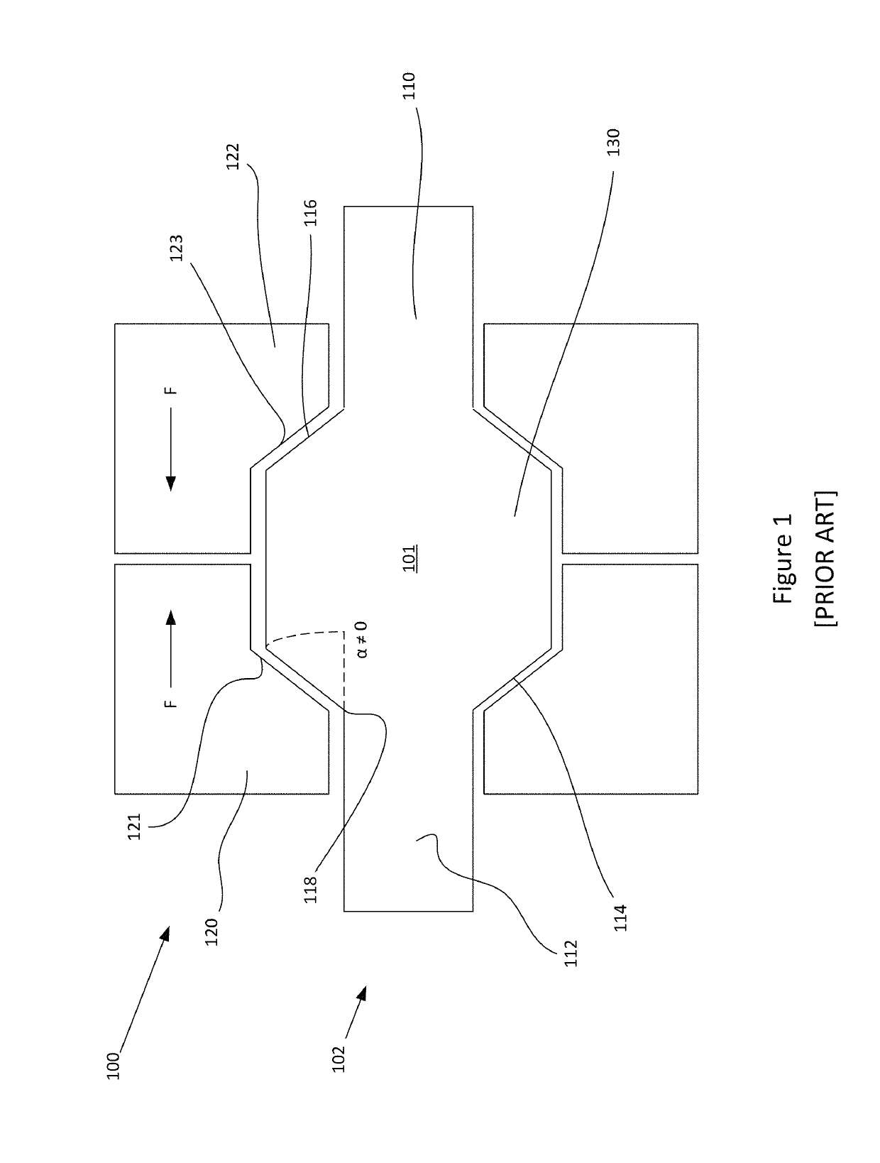
[0024]With reference to FIG. 1, a schematic cross-section of a Prior Art sealing apparatus 100 is provided. The Prior Art sealing apparatus 100 comprises a first fixture 120 and a second fixture 122 providing compressing forces F on the ceramic core 102...


PUM


Abstract

The present invention provides a system for providing a stress reduction apparatus for a ceramic electrical penetrator or pin in a subsea environment. More specifically, the present invention provides a deformable translatable seat in an annular pocket that prevents the transfer of shear forces from a shell or fixture to a ceramic electrical penetrator or pin. The present invention provides a relatively soft metal seat that conforms to the profile of the shoulder of a mating electrical penetrator or pin and deforms to reduce or eliminate concentrated bearing stresses. The deformable translatable seat may also shift and deform within the annular pocket to relieve shearing stresses exerted on the electrical penetrator or pin by the shell or fixture.

Description

FIELD OF THE INVENTION[0001]The present invention generally relates to an electrical power feedthrough. More specifically, the present invention relates to a method and apparatus for reducing stress or strain on a ceramic electrical penetrator in an electrical power feedthrough system in a subsea environment.BACKGROUND[0002]In subsea production, electrically operated apparatuses below sea level are typically supplied by power from sea- or land-based host facilities. The power is provided from the external sources to the subsea devices via cable conductors to submerged process control equipment, pumps and compressors, transformers, motors, and other electrically operated equipment. As these components are disposed subsea and are typically enclosed and protected by water-proof pressure vessels, power is provided by means of a cable termination and connector, which may be an electrical penetrator, designed to penetrate and provide power through a bulkhead.[0003]In existing penetrator a...

Claims


Application Information

Patent Timeline
Patent Type & Authority Patents(United States)
IPC IPC(8): H01R13/52H01R13/523H02G3/22H02G9/02H02G15/007
CPCH01R13/521H01R13/523H02G15/007H02G9/02H02G3/22
Inventor MCCLEARY, ALAN D.ELIASSEN, CHRISTOPHER M.
Owner TELEDYNE INSTR INC
Why Eureka
Try Eureka