Non-helical torsion spring system

a torsion spring and non-helical technology, applied in the direction of torsion springs, mechanical equipment, transportation and packaging, etc., can solve the problems of preventing composite or non-metallic construction, significant obstacles to the true torsion element, and failure of elements, etc., to achieve the effect of eliminating the stress of non-helical torsion springs

Inactive Publication Date: 2008-07-31
MC CLELLAN W THOMAS
View PDF22 Cites 2 Cited by
  • Summary
  • Abstract
  • Description
  • Claims
  • Application Information

AI Technical Summary

Benefits of technology

[0013]It is accordingly an object of the invention to provide a non-helical torsion spring system, which overcomes the hereinafore-mentioned disadvantages of the heretofore-known devices of this general type and which eliminates stresses in non-helical torsion springs.
[0014]With the foregoing and other objects in view there is provided, in accordance with the invention, a non-helical torsion spring system, comprising an arm to be connected to a load and at least one ring to be connected to a moving member. At least two torsion elements each have one end disposed at and resisting rotation relative to the arm but permitting flexural movement relative to the arm. The at least two torsion elements each have another end disposed at and resisting rotation relative to the at least one ring but permitting flexural movement relative to the at least one ring. Either the torsion element end at the arm or the torsion element end at the ring, or both, are movable axially, that is lengthwise. A torsion control is provided for adjusting torsion in the at least two torsion elements. The provision of multiple torsion elements rather than a helical or coil spring used in the prior art, greatly reduces or eliminates stresses. When used in a vehicle, the load is a frame or chassis of the vehicle and the moving member is a vehicle suspension member.
[0015]The system according to the invention eliminates stresses by providing a non-helical, true torsion system having two or more separate, small diameter, multi-centric torsion elements controlled in one or more separate groupings in which each element torsions freely from all other elements. The elements are free lengthwise at one or both end attachments to allow the elements to shift lengthwise in either direction to shorten or lengthen as they spiral and un-spiral. The element end attachments are rotationally resistive while still retaining two axis freedom in both length and flexion movements.

Problems solved by technology

Those stresses restrict spring loading, range of rotation, usable spring arc, cycle life and spring efficiency, while creating deformations within the torsion element, inducing element failure and preventing composite or non-metallic construction.
The first three stresses of the true torsion element are significant obstacles because they increase by the square of the radius of the element and prevent the construction of efficient, wide load range, controllable torsion spring systems.
Stresses are unavoidable in torsion because each particle or portion of the torsion element is in an unequal orbital arc or unequal three-dimensional motions compared to all other particles or portions of the element.
That reversing angle change creates a focus of destructive tension in a narrow zone directly across and completely through the torsion material.
All of those devices suffer from the stresses described above.

Method used


Image

  • Non-helical torsion spring system
  • Non-helical torsion spring system
  • Non-helical torsion spring system

Examples


Embodiment Construction

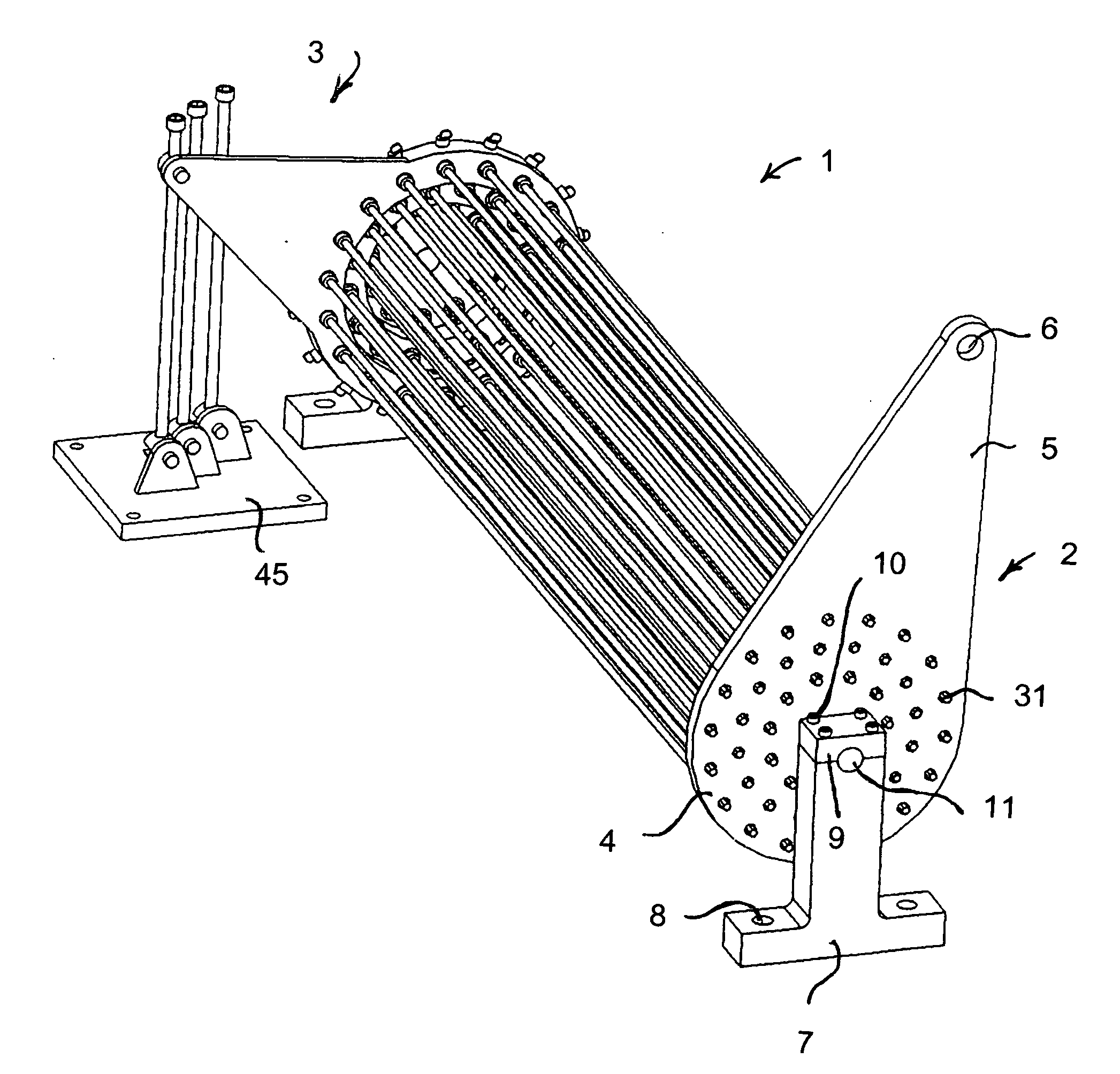
[0047]Referring now to the figures of the drawings in detail and first, particularly, to FIG. 1 thereof, there is seen a perspective view of a first, manual engagement embodiment of a torsion spring system 1 according to the invention, having a working or load end 2 and a control end 3. A working end ring 4, located at the working end 2, has a working arm 5 with an engagement opening 6 acting as a work or load attachment point, for instance for attachment to a vehicle chassis or frame. The working end ring 4 is mounted on a working end mount 7 having mounting holes 8, for instance for mounting on a moving member, such as a suspension member for a wheels of a vehicle. The mount 7 also has a cap 9 secured by bolts 10. A bearing opening 11 is formed by the mount 7 and the cap 10. The load could also be a building structure and the moving member a door, such as a garage door, preferably an overhead garage door.

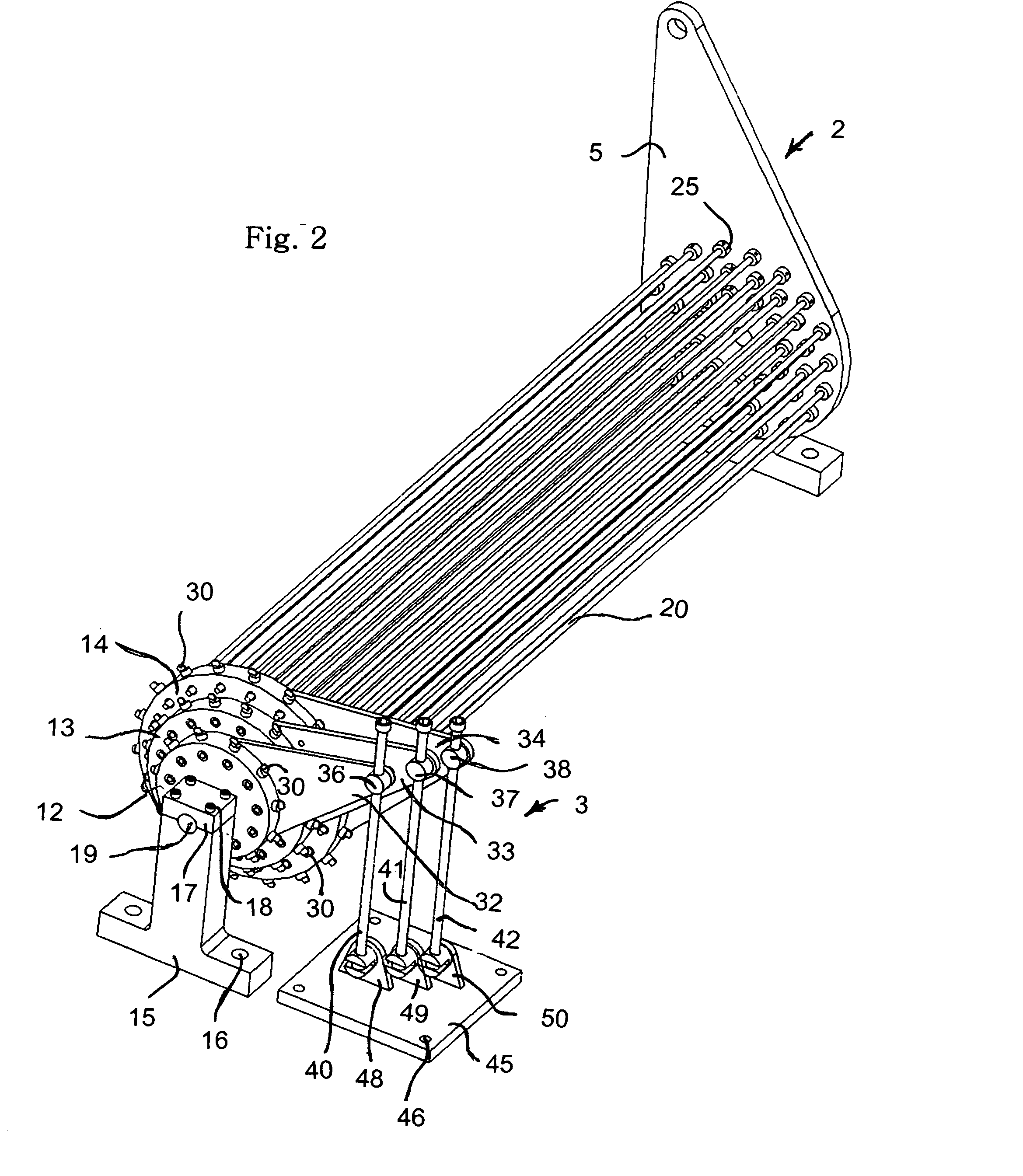
[0048]As is best seen in FIG. 2, three independent control rings 12, 13, 14 a...


PUM


Abstract

A non-helical torsion spring system includes an arm to be connected to a load, such as a frame or chassis of a vehicle, and at least one ring to be connected to a moving member, such as a vehicle suspension member. Torsion elements, which may be disposed in concentric groups, each have one end disposed at and resisting rotation relative to the arm but permitting flexural movement relative to the arm. The torsion elements also each have another end disposed at and resisting rotation relative to the at least one ring but permitting flexural movement relative to the at least one ring. At least one of the ends is axially movable. Each group of torsion elements is connected to a respective ring. A torsion control adjusts torsion in the at least two torsion elements, manually or through the use of servomotors.

Description

BACKGROUND OF THE INVENTION[0001]1. Field of the Invention[0002]The invention relates to a non-helical torsion spring system. Such a system may be used between a frame or chassis of a vehicle and a vehicle suspension member.[0003]2. Description of the Related Art[0004]True torsion springs or rods (non-helical or coil) are objects which twist the material of an object around the longitudinal axis of that object and as such are limited by the rapid onset of internal stresses created within the element. Those stresses restrict spring loading, range of rotation, usable spring arc, cycle life and spring efficiency, while creating deformations within the torsion element, inducing element failure and preventing composite or non-metallic construction.[0005]Helical or coiled springs, such as those disclosed in U.S. Pat. Nos. 5,464,197 and 4,961,743, or garage door springs, where only a configuration or “coil shape” of the object is referenced to rotate with respect to another “coil shape” of...

Claims


Application Information

Patent Timeline
Patent Type & Authority Applications(United States)
IPC IPC(8): F16F1/14
CPCB60G11/18F16F1/14B60G2202/13B60G11/185
Inventor MC CLELLAN, W. THOMAS
Owner MC CLELLAN W THOMAS
Why Eureka
Try Eureka